


High Steer Front 3-Link
(Rock Assault Housing)
Due to customer demand, Trail-Gear has designed their signature Trail-Link Three Front 3-Link Kit to be used with High Steer. Trail-Gear's Trail-Link Three Front 3-Link Kits are the only complete kits for Toyotas on the market today. This kit is affordable, user friendly, and strong. The Panhard is 1.25" x .250" wall DOM material, the other link material is 2" x .250" wall DOM tubing, and the rod ends are 1.25" Creeper Joints. The Panhard bracket on the axle is 3/16", all other brackets are 1/4" steel, formed and welded. The TG Engineers have designed kits to work with OEM or Rock Assault axle housings. With 14" shocks we are getting 40" to 50" of articulation depending on the suspension in the rear of the truck and the steering system.
This kit has been extensively tested and has proven itself to be another superior Trail-Gear suspension product. Kit includes everything you need, except shocks and upper shock mounts. You determine the upper shock mounting location based on the desired ride height and the needs of your vehicle.
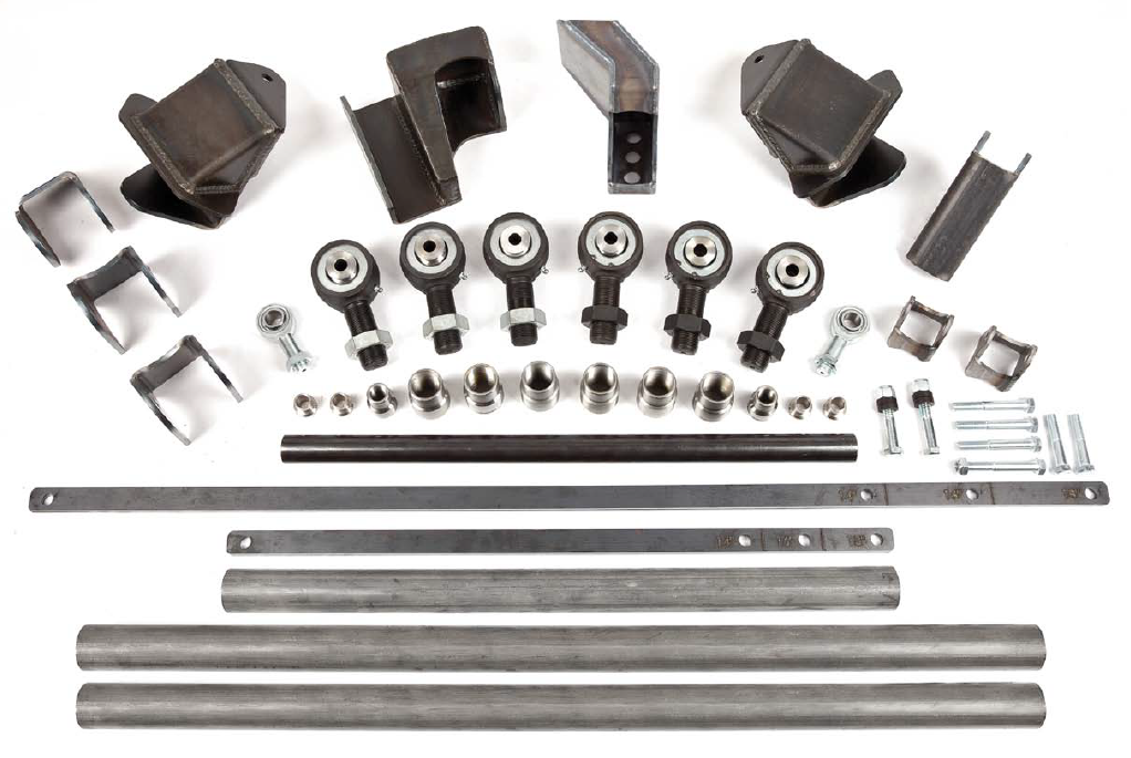
Kit Includes:
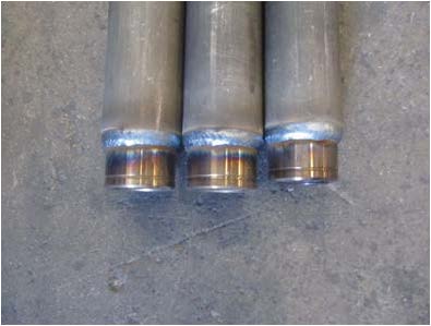
- (2) 41", 2" OD x .250" Wall DOM links
- (1) 30", 2" OD x .250" Wall DOM links
- (1) 27.50", 1.25" OD x .250" Wall DOM Panhard link
- (6) Creeper Joints
- (8) Weld-in bungs
- (2) Rod ends
- (4) Misalignment spacers
- (4) Shock length mockup strips
- (2) Lower shock mounting kits
- All necessary link mounting brackets
NOTE: If you plan to buy a housing for this product please use a housing with the bare short side truss. This kit is designed for use with High Steer. For full hydraulic steering systems.
| Note: Images are for illustration purposes only. Images may not represent the product listed. Please contact customer service with any questions or concerns: 1-928-505-2501. |
by Trail-Gear
- 1979-1995 Pickup (4x4)
- 1981-1995 4Runner (4x4)
To open a printable PDF version of this instruction CLICK HERE
Tools Needed:
- ⅜" & ½" Ratchets
- ½", 9/16", ¾", 1 ⅛", 12mm, 17mm, 19mm Sockets
- ½", 9/16", ¾", ⅞", 11/16", 1", 1 ⅛" Wrenches
- 7/32", â…" Allens
- Flathead Screwdriver
- Side Cutters
- Grinder
- Torch
- Welder
- Hammer
- Floor Jack and Jack Stands
- Torque Wrench
- Tape Measure
- Drill & 3/4" Drill Bit
- Power Steering Fluid (Royal Purple Recommended)
Installation Notes:
-
1. Read all instructions completely and carefully before you begin.
2. Check to make sure the kit is complete and that no parts are missing. If anything is missing, please contact Trail-Gear at (559) 252-4950.
3. Park vehicle on a clean, dry, at, level surface and block the tires so the vehicle can not roll in either direction.
Installation Instructions:
-
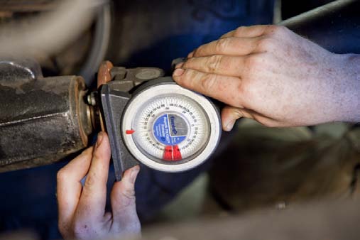
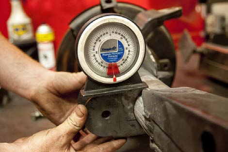
1. Before starting installation, take some measurements of your truck so that you can determine proper set up of your
new 3 link kit. Take these measurements at ride height on a level surface. Measure your current wheelbase and front
axle pinion angle. Record the data in the table on the last page of these instructions.

2. Mark the center-line of the front axle on each side of the frame. These marks will provide a reference when all brackets are cut off.
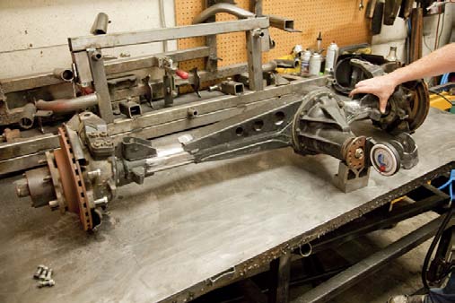
3. Remove axle, cut off front suspension of the truck, and grind smooth.

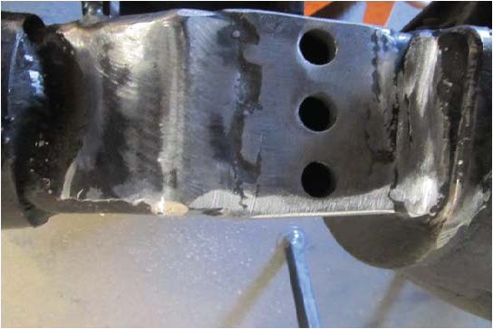
4. If you are using a OEM housing. Cut spring perches and shock mounts off of axle and grind smooth. If you are using a Rock Assault housing with spring perches already installed, you will need to leave the short side (passenger) perch in place and cut off only the front and rear portion of the perch leaving the truss in place.
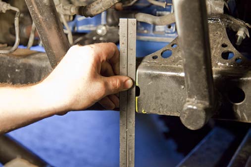
5. Position axle on bench and raise the pinion until the pinion angle matches the angle measured in step 1.
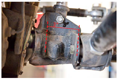
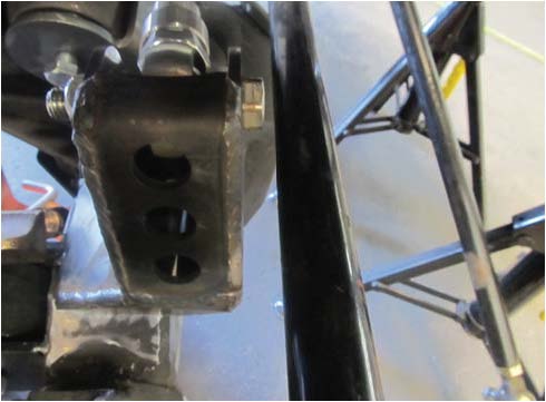
6. Mark axle 3 inches in from range on each side. Place the outside of the Lower Link bracket on the line and level them to the axle. This will place the link brackets level at ride height with the desired pinion angle. Tack weld them in place. If you are using a Rock Assault housing , place the brackets against the weld on the drop range. Approx 3" from the knuckle ball range.
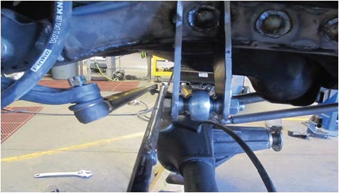
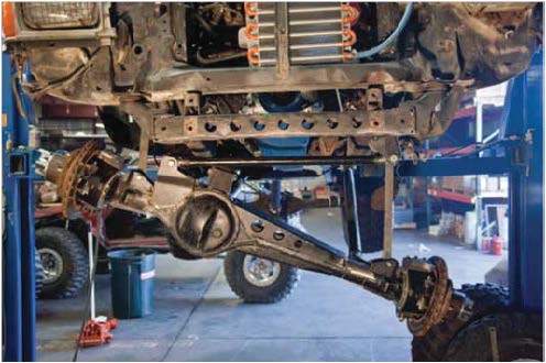
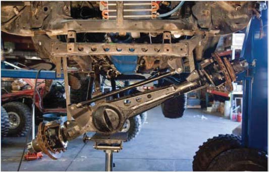
9. Place the vehicle at ride height. This will be critical if you are matching a leaf spring ride height in the rear. Place the axle in the desired position (forward/aft), and center it under the truck. Measure the length needed for the lower links(should be the same). Cut the tubing and tack the bungs into place. Install the joints and bolt the links into place. Ensure the tie rod and drag link are parallel.
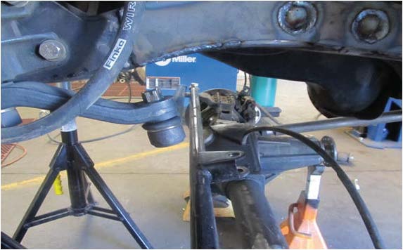
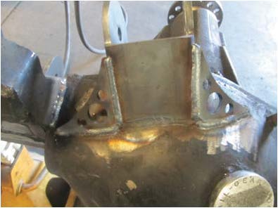
10. With the axle set in position forward and aft, and centered, place a jack stand under the pinion and set the previously measured pinion angle. Place the upper link bracket on top of the axle(the exact placement will vary from truck to truck). It is best to "cheat" the bracket out over the diff to allow room for the pan hard bar to compress past the bracket. The link bolt should be about flush with the differential mounting surface.
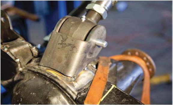
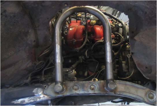
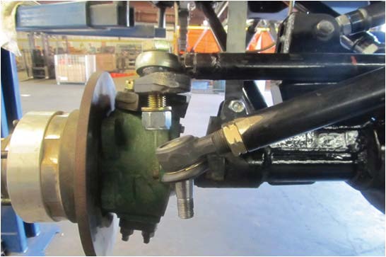
11. With the axle completely located, Install the axle side panhard bracket. If you are using Rock Assault housing , place the bracket in top of the old spring perch and tack in place. With the tie rod in place , turn the steering lock to lock to ensure the tie rod does not contact the panhard bracket.
12. Tack the bungs into the panhard tube and install rod ends. Bolt the panhard to the axle side bracket. Bolt the frame side bracket to the other end of the panhard. Now swing forward and aft until the panhard bar is parallel with the tierod, and is at the same downward angle as the drag link. Once this is set , tack the bracket into place.
13. Cut shock "mock-up" strips to the proper application length for the shock that you will use. We recommend 14" shocks for this kit. Note: These shock strips will only work with Fox 2.0 air shocks.
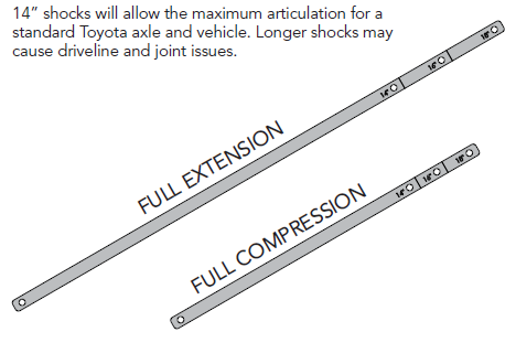
13. Continued - Once all links and panhard have been installed, raise the vehicle/ lower the axle to maximum droop. The upper link will touch the bottom of the upper link bracket and or the u joint will start to bind. This will be full extention when shocks are installed. Using the shock strips as a guide, fabricate suitable shock mounts(we used a 15" hoop as an example). With the long shock strips installed (full droop) ensure that the drag link will drop bellow the steering arm and is not bound up.
13. Continued
13. Continued
14. Once you have set full droop, compress the axle and install the short shock strips. Ensure the panhard is not contacting the oil pan (this may not always be possible). If the panhard is contacting the oil pan you will need to limit the suspension up travel to accommodate by using bump stop's(recommended). Also , ensure that the tie rod end at the pitmen arm does not contact the tie rod tube when suspension is compressed.
15. Using the shock strips, ex the suspension to full compression, full extension, full ex right and full ex left. Verify that there is no binding or metal to metal contact
16. Install air shocks, do not pressurize. Flex suspension again. Check for shock clearance with the frame, tires, and shock mounts. Flex to full compression, full extension, full flex left, and full flex right.
17. Remove shocks and links. Fully weld all brackets, paint as desired and reinstall all shocks and links.
17. Continued
18. Add nitrogen pressure to shocks. We recommend 3"-4" of up travel at ride height.