Non-Smog")
 Non-Smog")
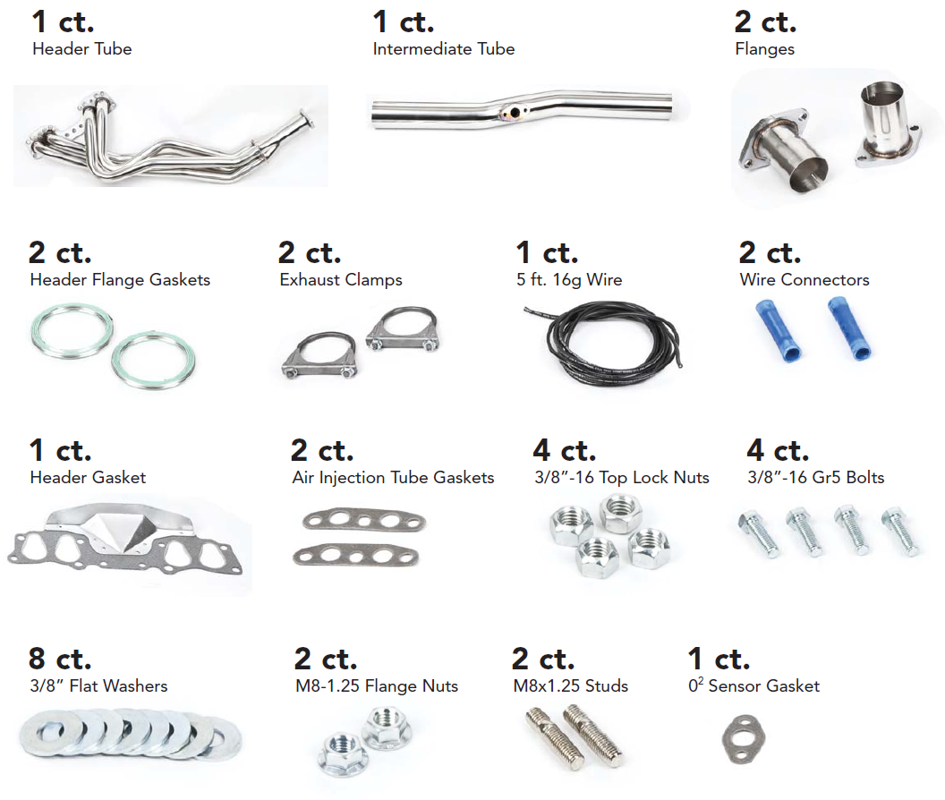
Rock Ripper Header Kit
Trail-Gear has raised the bar yet again in the Toyota Off Road Industry with the newest addition to its product line, stainless steel, 50 state legal Toyota header. Trail Gears header features 100% polished stainless steel 1/16" thick tubes going into a 1/2" thick header to head mounting flange. Trail Gear tig welded everything and then polished it to give it a clean look.
The Rock Ripper Toy Header is made out of stainless steel so it will not rust or corrode and does not need to be ceramic coated or wrapped. The Rock Ripper Toy Header is plug and play, and all gaskets, connectors, and pipes are included along with full color instructions.
NOTE: This header is not smog legal.
| Note: Images are for illustration purposes only. Images may not represent the product listed. Please contact customer service with any questions or concerns: 1-928-505-2501. |
by Trail-Gear
- 1979-1980 20R 2.2L Pickup Engines 4X4
- 1981-1984 22R 2.4L Pickup Engines 4X4
- 1981-1984 22R 2.4L 4Runner Engines 4X4
- 1983-1984 22RE 2.4L Pickup Engines 4X4
- 1983-1984 22RE 2.4L 4Runner Engines 4X4
To open a printable PDF version of this instruction
CLICK HERE
Tools Needed:
- ⅜" Ratchet & extensions
- 9/16", 12mm, 14mm, 17mm Sockets
- 9/16", 12mm, 14mm, 17mm Wrenches
- Hammer
- Floor Jack and Jack Stands
- Torque Wrench
- Chop Saw/Cutoff Wheel
- Electrical Crimpers
- Tape Measure
Installation Notes:
-
1. Read all instructions completely and carefully before you begin.
2. Check to make sure the kit is complete and that no parts are missing. If anything is missing, please contact Trail-Gear at (559) 252-4950.
3. Park vehicle on a clean, dry, at, level surface and block the tires so the vehicle can not roll in either direction.
Installation Instructions:
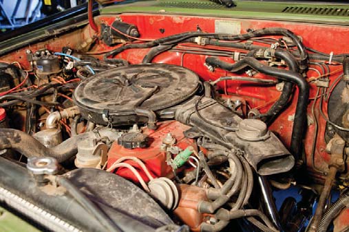
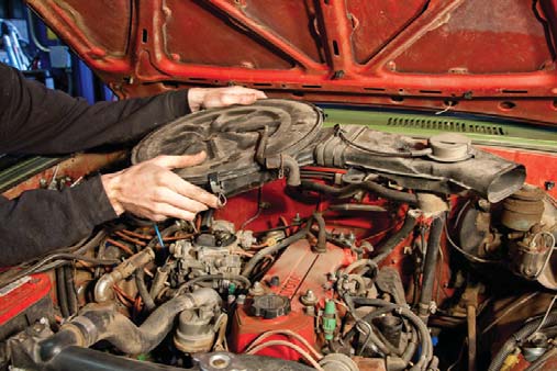
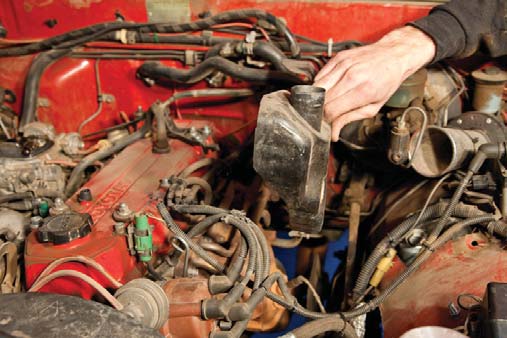
1. Jack up the vehicle, secure it on jack stands, and remove the air cleaner system. Ensure all wires and/or hoses are disconnected before removing.
2. Remove the heat shield covering the stock header.
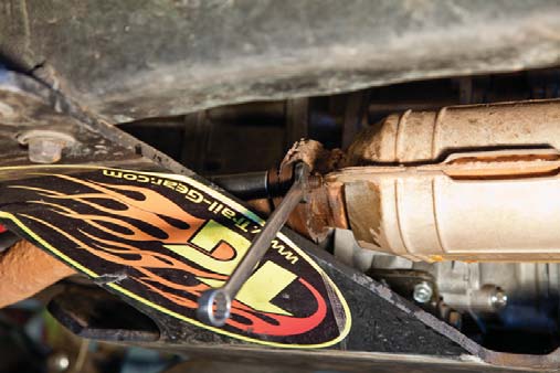
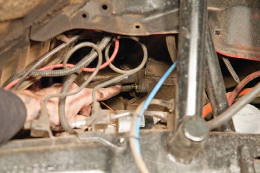
3. Disconnect the O2 sensor.
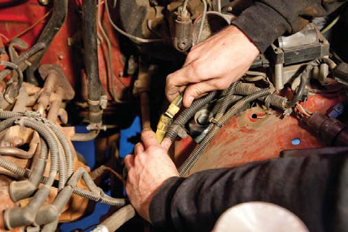
4. Remove the O2 sensor from the header.
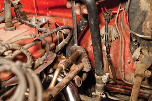
5. Remove the clamp securing the intermediate header tube.
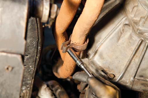
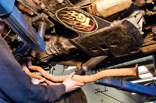
6. Unbolt and remove the intermediate header tube connecting the exhaust manifold to the catalytic convertor.
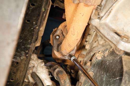
7. Unbolt the intermediate tube from the catalytic convertor.
8. Remove the intermediate tube.
9. Remove the old intermediate tube bracket.
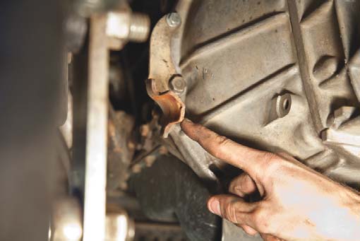
10. Remove secondary heat-shield from the frame.
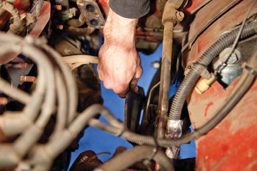
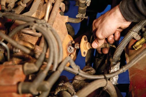
11. Remove the nuts that attach the header to the air injection crossover tube. Remove the two bolts attached to the air injection crossover tube located on the underside of the front passenger side of the truck. Follow the air injection crossover tube to the bracket that attaches the tube to the header to find these two bolts.
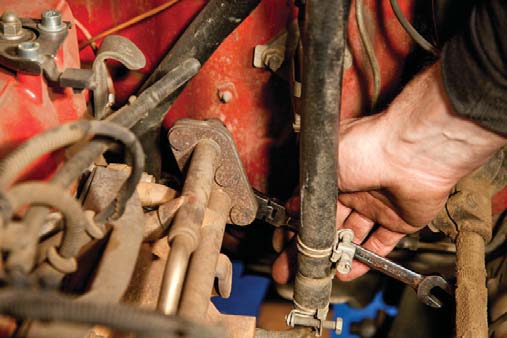
12. Pry the air injection crossover tube off of the studs on the air injection tubes.
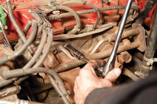
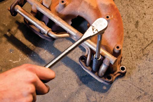
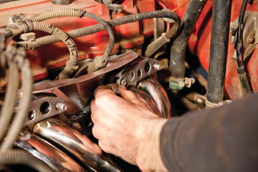
13. Use penetrating oil on all bolts and take extra care not to break the heads off. Unbolt and remove the exhaust manifold.
14. Remove the air injection tubes from the stock header. This step is optional. If you are installing this header in a non-smog certified vehicle, you should skip this step, but remove the air injection crossover tube, and cap off any open holes. Exhaust blockoff plate available.
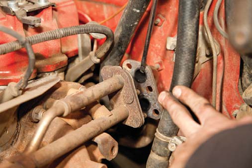
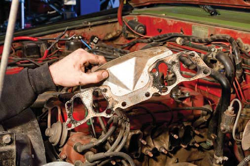
15. Remove the old gasket and clean gasket surface. Install new gasket supplied in kit.
16. Slide header into place and over the studs, ensuring you have replaced the gasket.
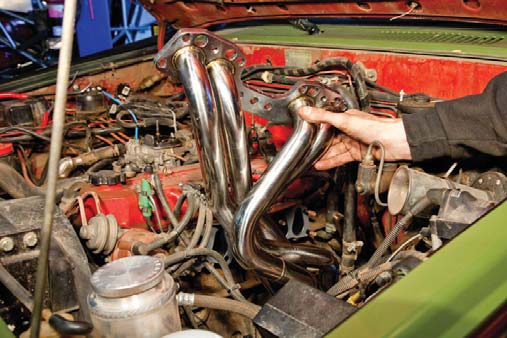
17. Apply anti-seize lubricant to the studs.
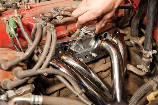
18. Install the two new gaskets onto the studs over the header.
19. Install the air injection tubes onto the new header. This step is optional. If you are installing this header in a non-smog certified vehicle, you should skip this step, but remove the air injection crossover tube, and cap off any open holes.
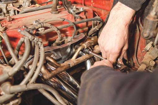
20. Slide the air injection crossover tube over the studs on the air injection tubes and tighten nuts. Remember to reinstall the nuts on the underside as well.
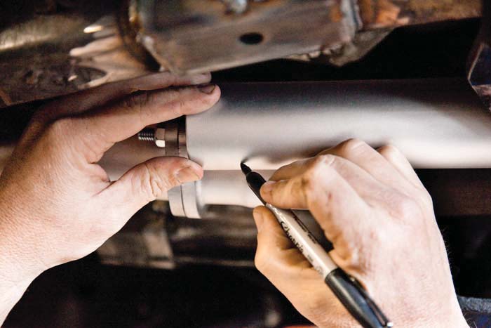
21. After connecting the flanges, mark the intermediate tube on each side just before the flange tube tapers. Cut the intermediate tube to the marked length.
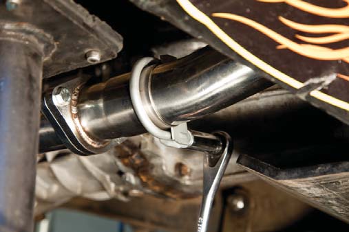
22. Slide the intermediate tube into place and insert the flange gasket between the intermediate tube and the catalytic convertor.
23. Insert and tighten bolts at the front and back of the intermediate tube.
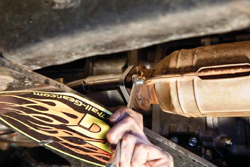
24. Install and tighten clamps onto the front and back of the intermediate tube. If possible you may TIG weld these instead.
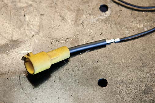
25. Lengthen the wire connecting to the O2 sensor as required.
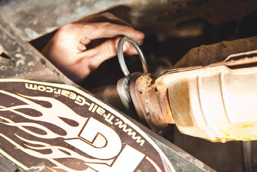
26. Install O2 sensor studs into the header tube as shown.
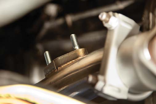
27. Install O2 sensor with new gasket over the studs in the header tube and tighten nuts.
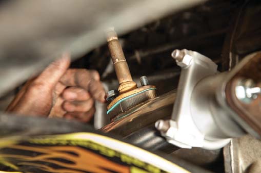
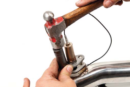
28. Due to different manufacturing tolerances for the O2 sensor, the slight tapping of a hammer with a socket may be necessary to install the sensor. Alternatively, some slight dremeling of the outside of the holes may be required.
29. Plug in O2 sensor.

30. Before starting your truck, wipe down all polished surfaces of the header and intermediate tube with alcohol.
31. Reinstall air cleaner back onto truck, ensuring that any hoses and wires are reconnected.