
")
")
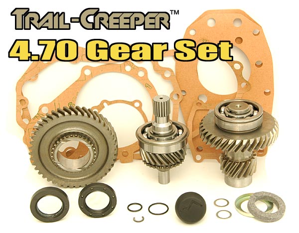
Trail Creeper Transfer Case Gears
(4.70:1 / 23-Spline)
For rock crawling, lower transfer case gears give you the control you need to keep your truck on track. Now, an affordable 4.70:1 gear kit for your gear driven Toyota transfer case. Trail-Creeper T-Case gears are available in 21 and 23 spline configurations. Input gears are precision ground & micro-polished to guarantee the removal of all surface imperfections in the forging. Gear sets reduce the stock low range from 2.28 to 4.70, nearly twice the reduction of the stock gears. High range is not affected and remains 1 to 1. Each gear set carries a full lifetime guarantee. If your gears ever fail to function properly, simply return them to us for replacement.
Kit Includes:
- Gears
- Gaskets
- Seals
NOTE: Disassembly and modification of transfer case is required for installation.
| Note: Images are for illustration purposes only. Images may not represent the product listed. Please contact customer service with any questions or concerns: 1-928-505-2501. |
by Trail-Gear
- 1979-1995 Pickup's 4x4 ( w/ Gear Drive Style Transfer Case)
- 1981-1995 4Runners 4x4 ( w/ Gear Drive Style Transfer Case)
To open a printable PDF version of this instruction CLICK HERE
Kit Includes:
Tools Needed:
- ⅜ Ratchet
- 12mm, 14mm, 30mm Sockets
- Air Wrench
- Needle Nose Pliers
- Hammer
- Grinder
- 3/16 Diameter Pin Punch
- Snap Ring Pliers
- 6mm Allen Wrench
- Gasket Scraper
- Flat Blade Screwdriver
- Adjustable Wrench
- Permatex® Ultra Grey® Silicon
What is the difference between 21 and 23 Spline Gears?
The transfer case input gear is the gear that slides into the transmission. V6 and turbo transmission use a 23 spline gear that is slightly larger than the 21 spline gear used on 4 cylinder transmissions. On a single transfer case you must use the gear type that matches the transmission. If you are building a dual transfer case assembly, the front case input gear must match the transmission output gear. The rear case of a dual transfer case can be set up with either 21 or 23 spline gears. When purchasing a dual transfer case adapter you can choose to purchase a 21 or 23 spline version. The only difference between a 21 and 23 spline dual adapter is the coupler that connects the front and rear case. It is important to match the dual adapter and rear gear set. If your rear case is going to run the stronger 23 spline gears you must also run a 23 dual adapter coupler. If your rear case is going to use 21 spline gears, then the dual adapter coupler must also be 21 spline.
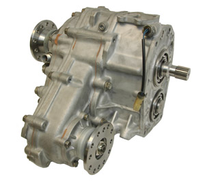
In a dual transfer case with 21 spline gears in both cases the weak spot and most common failure point is the input gear to the rear case. A dual transfer case built with 21 spline gears in the front case and 23 spline gears in the rear case is stronger and now the most likely point of failure becomes the rear output shaft. If you"˜re purchasing both a dual adapter and 4.70 gears for the rear case, order both in 23 spline. There is no cost difference building with 23 spline parts if you order both the dual adapter and gears in 23 spline configurations. In these instructions we refer to different transfer case housing sections by number. The pictures below show each of the housings and its number.

Installation Instructions:
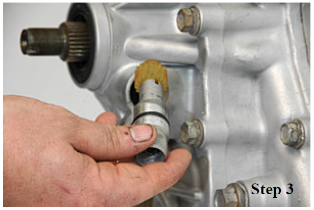
2. Remove the speedometer sender bolt.
3. Remove the speedometer sender.
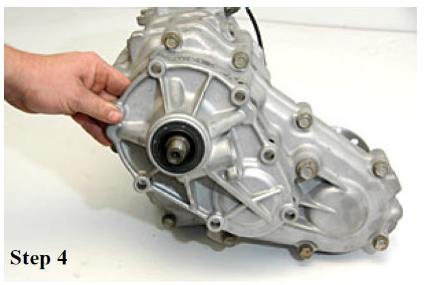
4. Remove the 7 bolts holding housing #4. Pull off the housing and remove.
5. Using snap ring pliers, remove the outer snap ring from the 4wd idler shaft bearing.

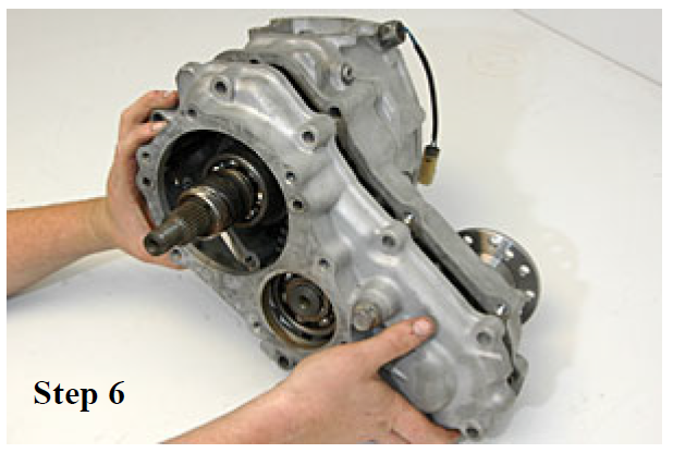
6. Remove the 10 bolts holding housing #3 and slide the housing out.
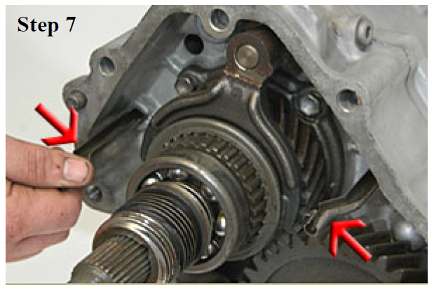
7. Remove the 2 oil galleys by gently pulling them straight out.
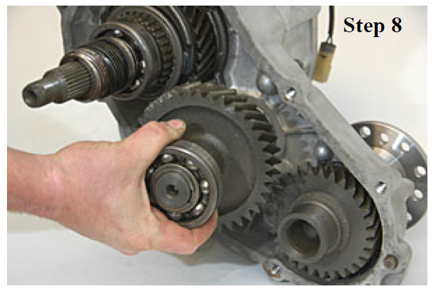
8. Remove the front output idler gear.
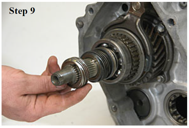
9. Remove the speedometer drive gear.
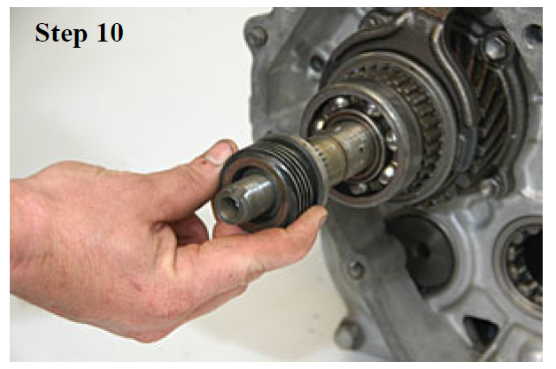
10. Remove the oil pump gear and the lock ball.
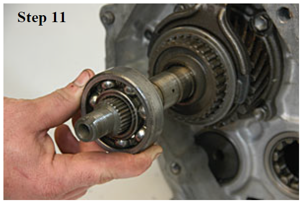
11. Remove the 63/28N bearing from the rear main shaft.
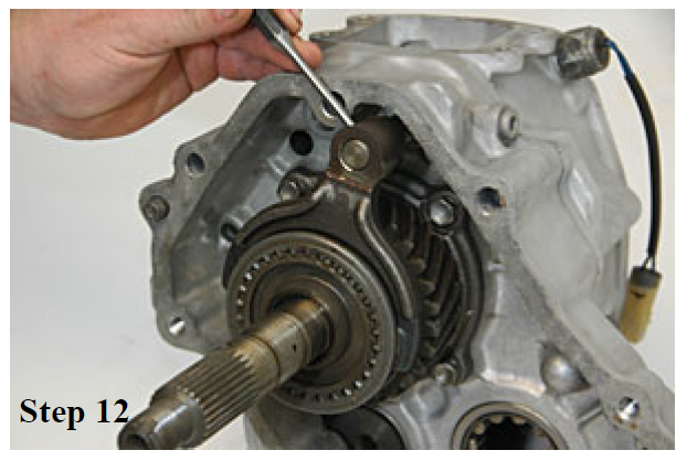
12. Shift into 2wd high. Remove the 2wd/4wd shift fork roll pin with a 3/16" pin punch.
13. Remove the 2wd/4wd shift hub.
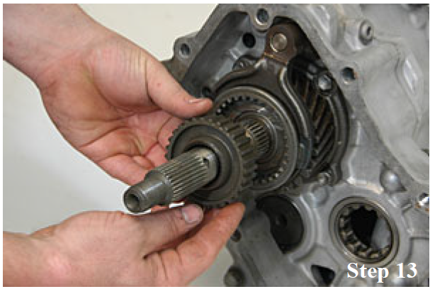
14. Remove the 2wd/4wd shift collar & fork.
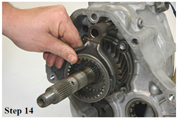
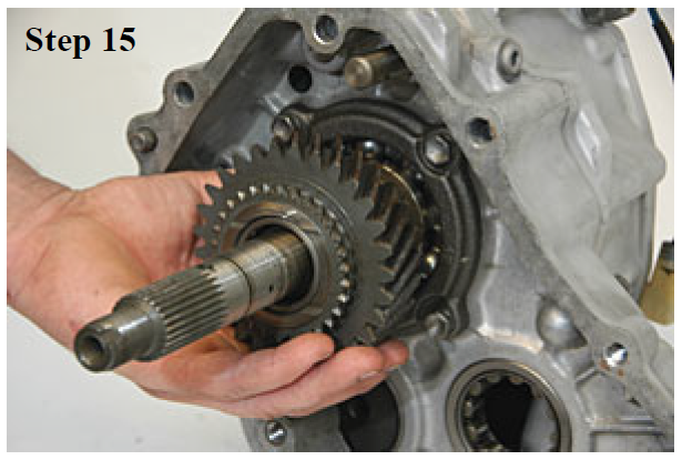
15. Slide off the front output gear from the output shaft.
16. Remove the pair of cage bearings from the output shaft.

17. Remove the thrust washer and locking ball.
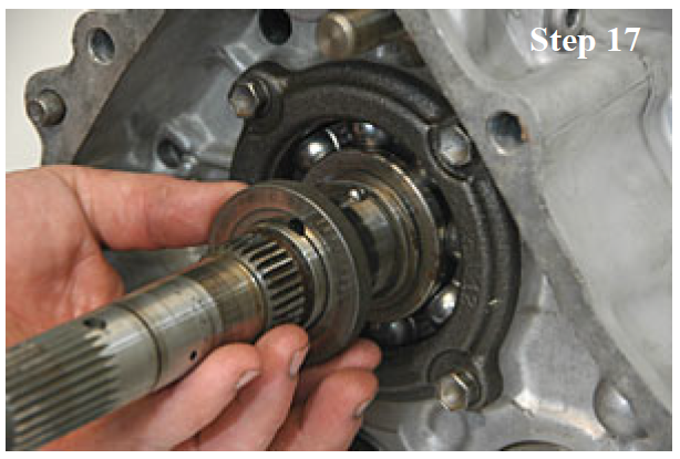
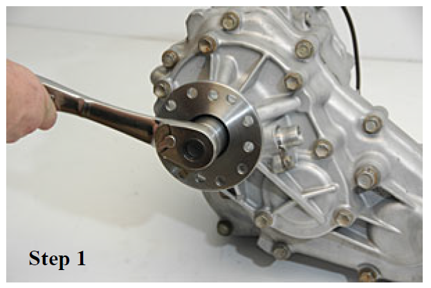
18. Remove the front output 30mm nut and the flange.

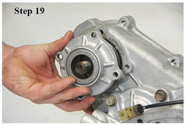
19. Remove the 4 bolts holding housing #5. Slide housing #5 off.
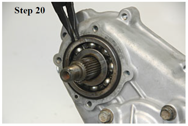
20. Remove the snap ring from the front output bearing.
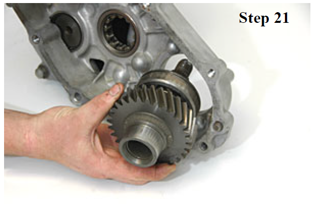
21. Remove the front output gear.
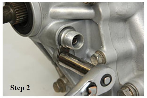
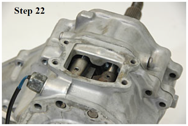
22. Unbolt and remove the shifter base or block offplate depending on the model.
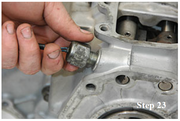
23. Remove the 4wd light switch.
24. Using an Allen wrench, remove the detent plugs from both sides of the case. Rotate the case on it's side, and tap the case lightly to allow the spring and ball to fall out.

25. Remove the 2 bolts holding housing #1 on the passenger side of the case.

26. Remove the last 2 remaining bolts holding housing #1 on the driver side of the case.

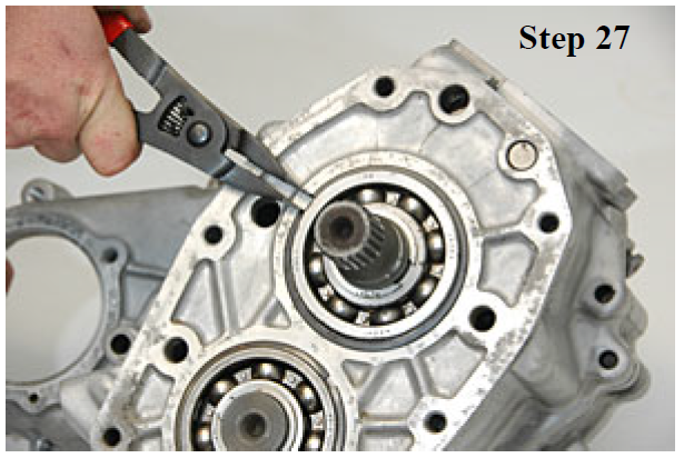
27. Remove the snap ring from the input shaft bearing.
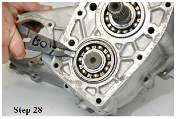
28. Remove the snap ring from the idler shaft bearing.
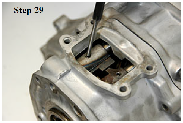
29. Using a pin punch, drive out the roll pins from each of the shift rails. Let the pins fall into the case.
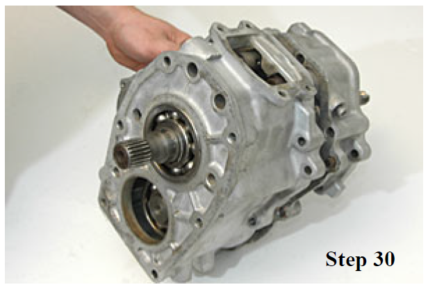
30. Slide housing #1 forward and remove. Retrieve the two shift fork roll pins from the bottom of the housing.
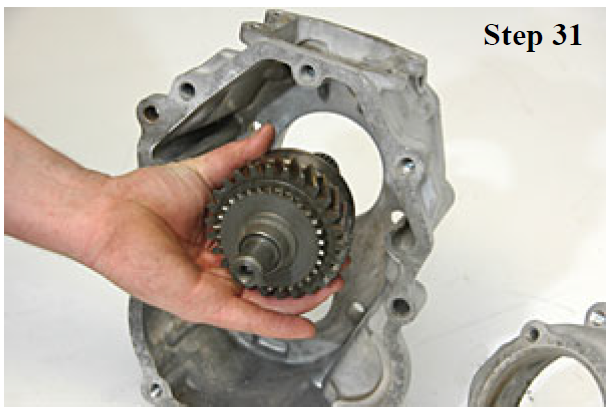
31. Remove the input gear.
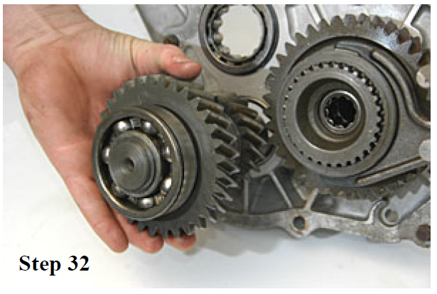
32. Remove the counter shaft gear.
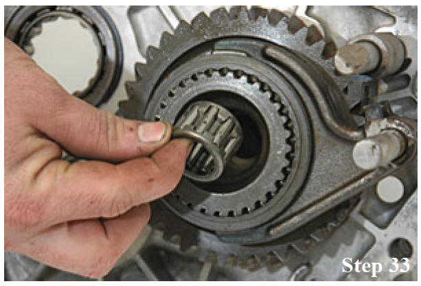
33. Remove the pocket bearing from the inside of the main shaft.
34. Remove the 2wd/4wd shift fork.

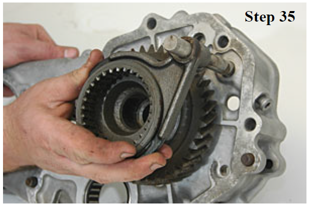
35. Remove the hi/lo shift fork along with the shift collar.
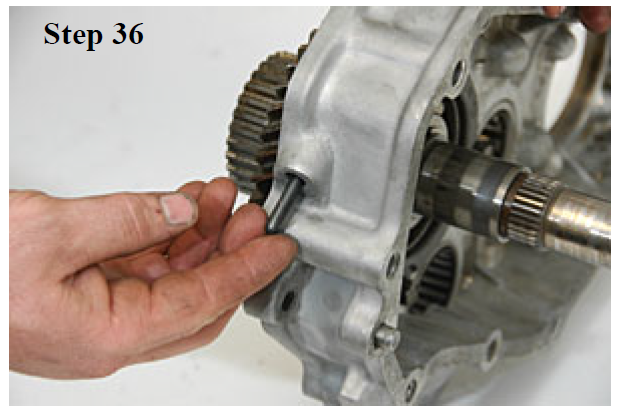
36. Turn the transfer case upside down and remove the shift fork interlock pin from the detent plug hole.
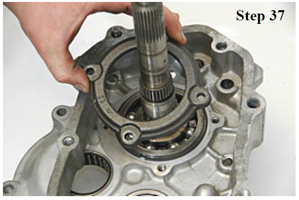
37. Remove the 4 bolts holding the main shaft bearing cover. Remove the cover.
38. Remove the snap ring on the main shaft bearing.

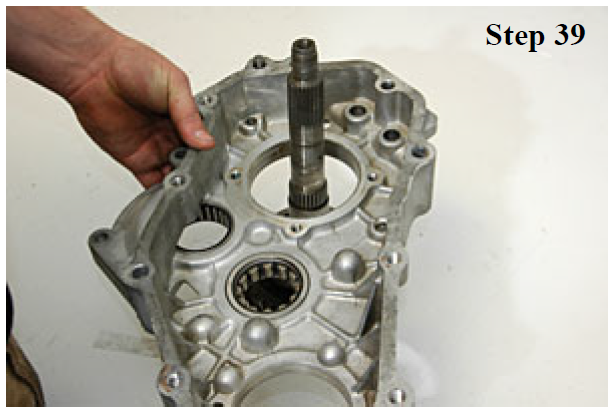
39. Slide housing #2 off of the main shaft.
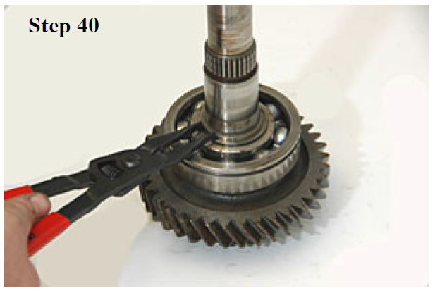
40. Remove the snap ring from the main shaft.
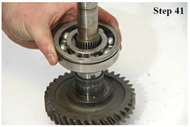
41. Remove the 6208N main shaft bearing using a gear puller or press.
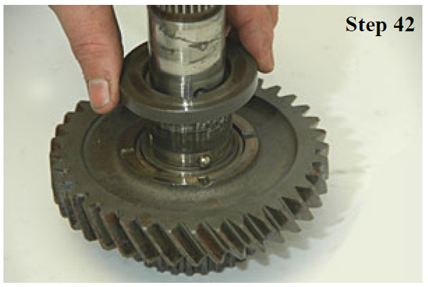
42. Remove the thrush washer and lock ball from the main shaft.
43. Remove the low speed gear from the main shaft. Discard the low speed gear.

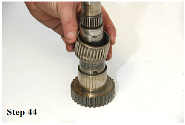
44. Remove the cage bearing from the main shaft.
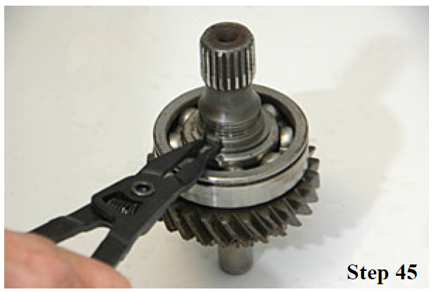
45. Remove the snap ring from the input gear. Discard the bearing and the input gear.
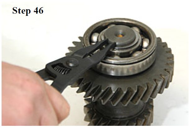
46. Remove the snap ring counter shaft gear. Discard the bearing and the counter shaft gear.
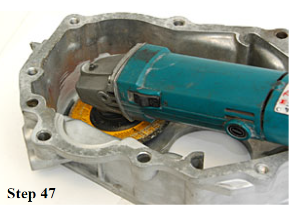
47. Using an end mill or hand grinder clearance case as required to accept the new 4.70 counter shaft.
48. Install the counter shaft and bearing into the housing and spin to verify the clearance between the gear and housing.

49. Using a hand grinder, remove about 1/8" of aluminum from housing #1 near the oil galleys.

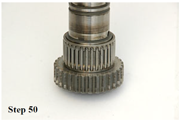
50. Apply bearing grease to the bottom of the main shaft and the install low speed needle bearing. Apply another layer of grease on to the outside of the needle bearings.
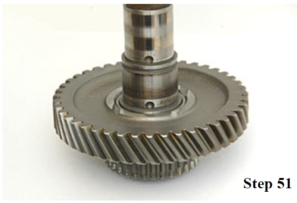
51. Slide the new 4.70 low speed gear onto the main shaft and over the needle bearings.
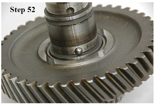
52. Apply grease to the lower main shaft ball hole. Insert the ball into the hole.
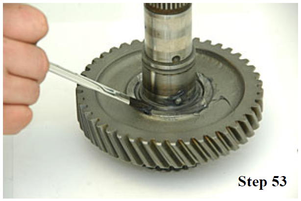
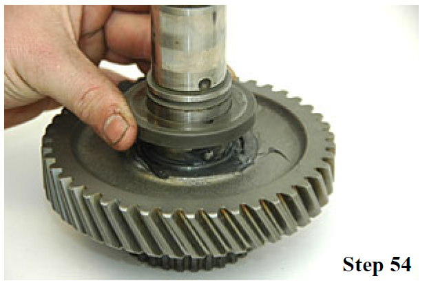
53. Apply axle grease to the top face of the low speed gear as shown above.
54. Slide the thrust washer into place, lining up the notch in the washer with the lock ball from the previous step.
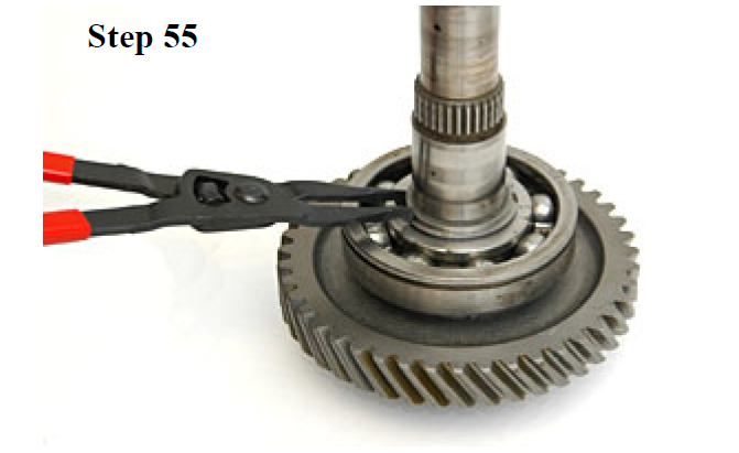
55. Slide the 6308N down onto the thrust washer. Press the bearing down until it contacts the thrust washer and the snap ring grove is visible. Install the snap ring above the bearing on the main shaft.
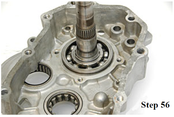
56. Slide Housing #2 onto the main shaft and seat housing on the 6308N bearing.
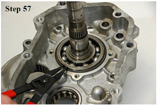
57. Install the snap ring on to the outside of the 6308N bearing.
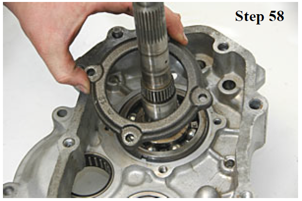
58. Slide the bearing retainer over the main shaft and into place.
59. Install the 4 retainer bolts and torque to 10 ft/lbs.

60. Using a grinder or file, clearance the shift fork and block as shown.

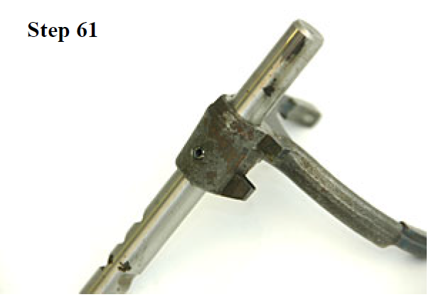
61. Insert the roll pin into the low range shift fork. The shaft can go in two ways, install as shown above. Notice the position of the notches on the shift rail during assembly.
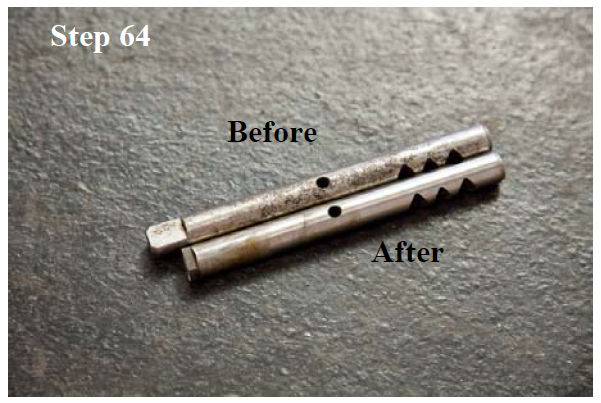
62. If your case has this hi-lo shift rail, follow step 63, otherwise, move on to step 65.
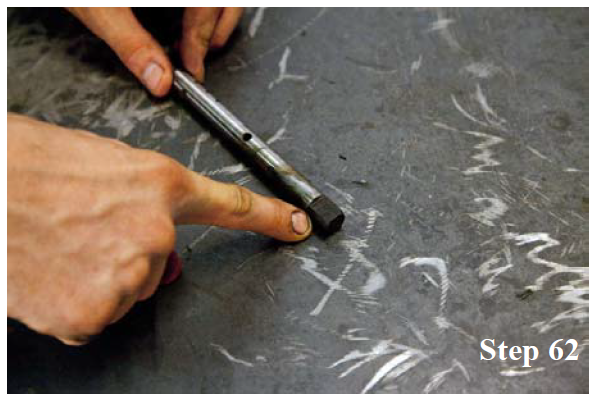
63. Perform this step only after reviewing step 62. Cut 3/8" off of the flat side of the hi-lo shift rail.
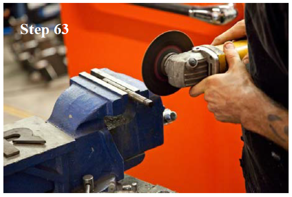
64. After cutting, your shift rail should look like the bottom one in the image above.
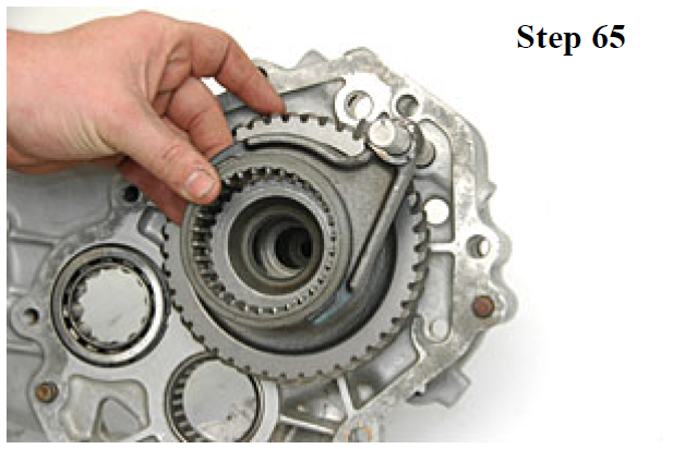
65. Place the clutch sleeve into the shift fork and slide the fork into place.
66. Grease the high/low pocket bearing inside and out. Insert the bearing into the main shaft.

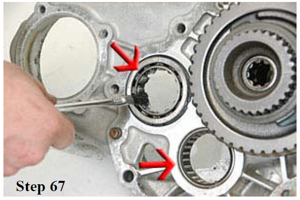
67. Grease both and the counter shaft and the idler bearings as shown.
68. Install the counter shaft gear/bearing assembly as shown.

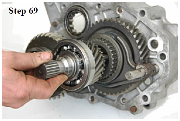
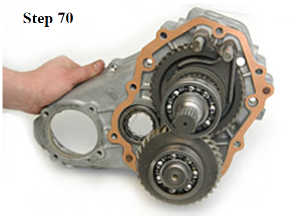
69. Install the input gear/bearing assembly into the main shaft.
70. Place the new gasket onto housing section #2.
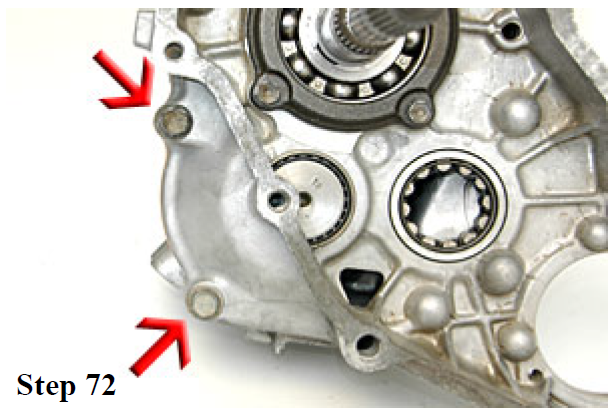
71. Slide housing #1 into place and install the bolts as shown. Using a rubber hammer, apply gentle pressure to seat the housing.

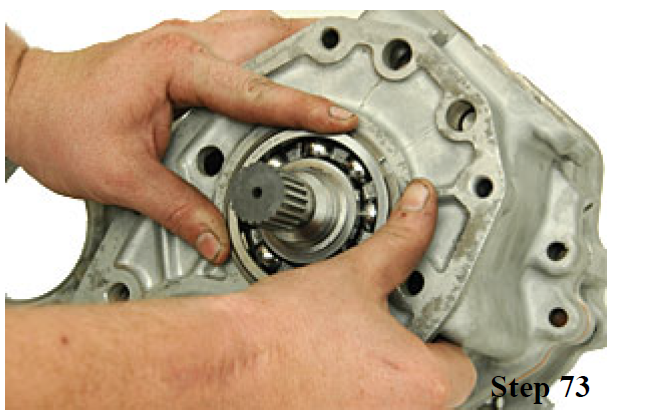
72. Turn the transfer case around and install two more bolts on the other side.
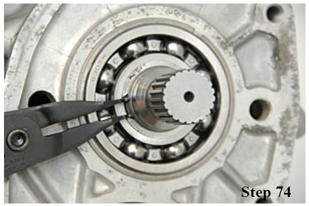
73. Install the outer snap ring on the input gear bearing.
74. Install the inner snap ring onto the input gear bearing.
75. Install the outer snap ring on the counter-shaft bearing.
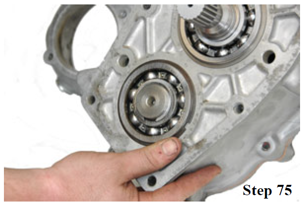
76. Install the inner snap ring onto the counter-shaft gear bearing.

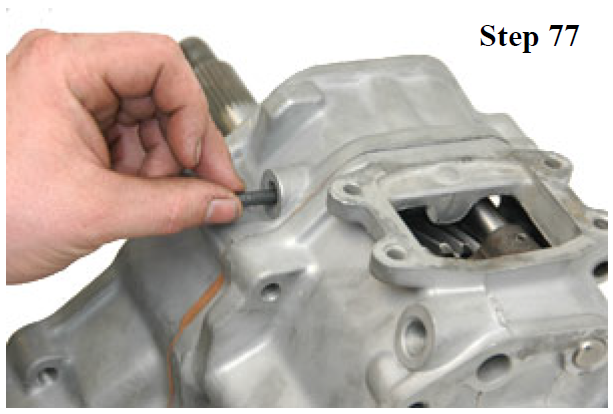
77. Insert the interlock pin into the driver side detent hole. If installing a twin stick shifter skip this step. Turn the case on it's side to assist in getting the pin to drop into place.
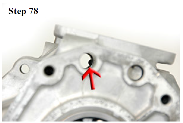
78. Make sure the interlock pin is all the way into position. Here the end of the pin can still be seen through the shift fork hole. Adjust the position of the shift fork until the pin can go all the way out of view.
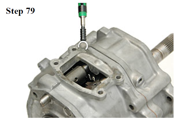
79. Install the shift rail and shift block. On models with a C-clip replace the clip with the one provided. Install the clip as shown.
80. Use a 3/16" pin punch to drive the high low shift fork pin into place.

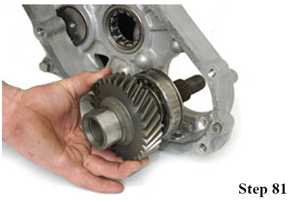
81. Reinstall the front output gear with the bearing into housing #2.
82. Install the snap ring on the front output bearing.

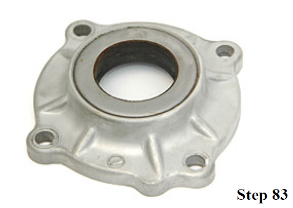
83. Replace the seal and felt on housing #5. Grease the inside of the rubber seal surface.
84. Place the front output gasket onto the face of housing #2.

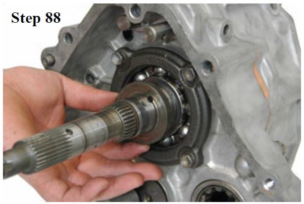
87. Place the ball into the ball hole on the main shaft.

88. Align the thrust washer with the lock ball and slide it into place over the ball. Add grease to the face of the thrush washer once in place.
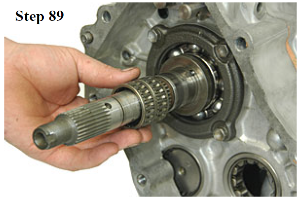
89. Grease the inside and outside of the output shaft cage bearings. Slide bearings into position on the main shaft.
90. Install the front output drive gear onto the main shaft.
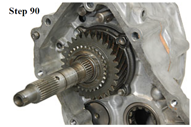
91. Grease the outer face of the front output drive gear.

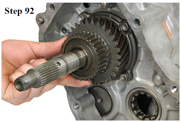
92. Slide the clutch hub into place on the main shaft.
93. Place the clutch sleeve into the shift fork. Slide the shift fork and clutch sleeve into the case.

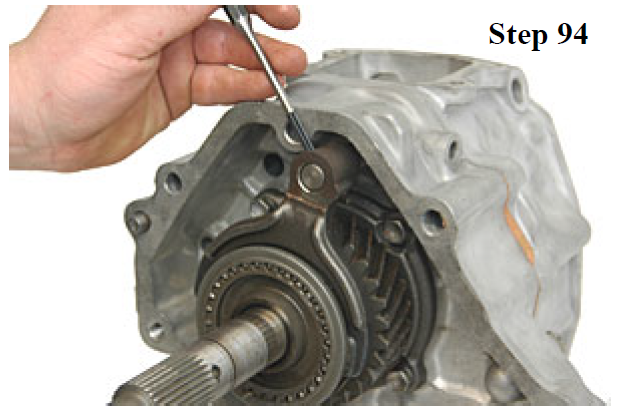
94. Using a 3/16" pin punch, drive the shift fork roll pin down until it is flush with the fork.
95. Reinstall the front drive idler gear.

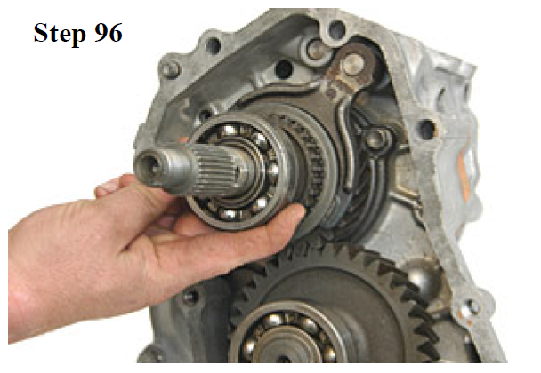
96. Install the output shaft rear support bearing.
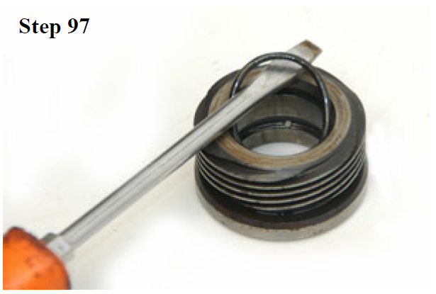
97. Using a screwdriver, remove and replace the oil pump seal inside the oil pump drive gear.
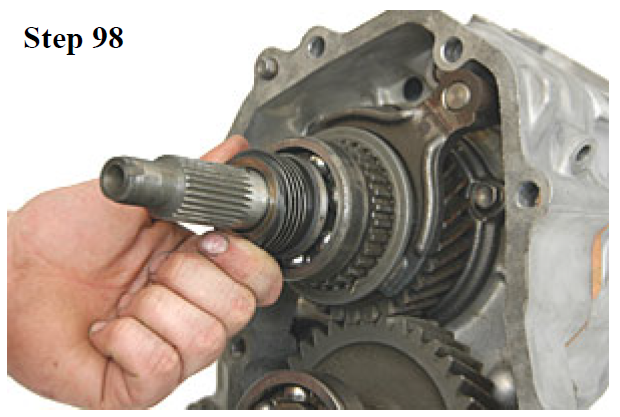
98. Slide the oil pump drive gear onto the main shaft until it seats on the bearing.
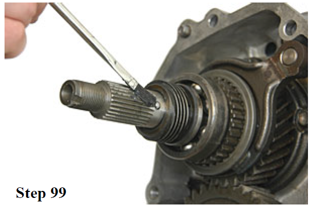
99. Apply grease to the ball hole. Place the ball into the hole.
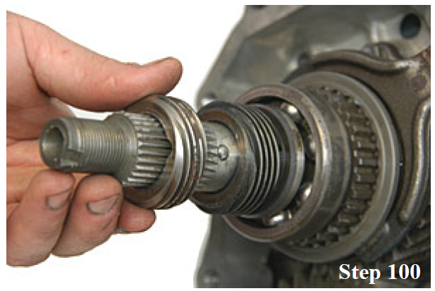
100. Align the notch in the speedometer drive gear with the ball on the main shaft. Slide the speedometer drive gear onto the main shaft.
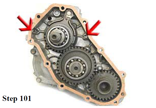
101. Place the new gasket onto the back of housing #2. Reinstall the oil delivery tubes at the arrows.
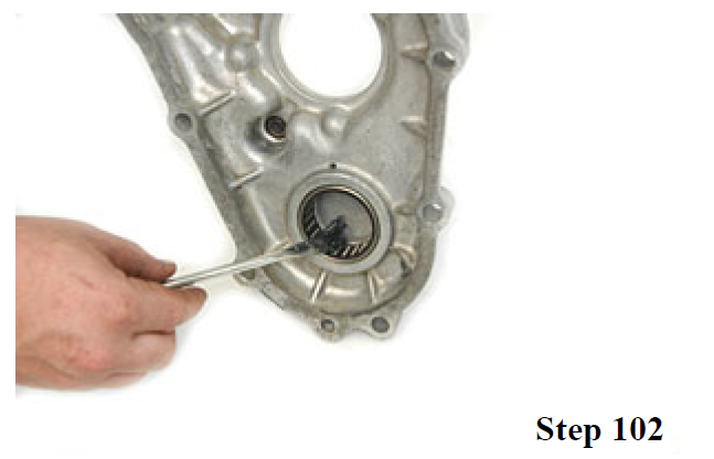
102. Apply grease to the cage bearing in the back of housing #3.
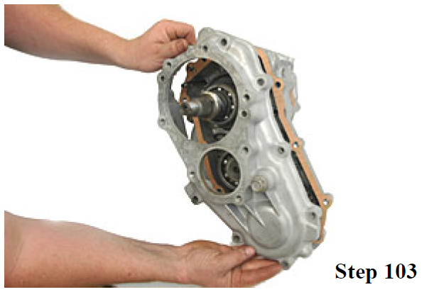
103. Install housing #3 onto the back of housing #2. Align the oil transfer tubes with the slots in the back of housing #3. Install 10 bolts into cover #3. Torque to 30 ft/lbs.
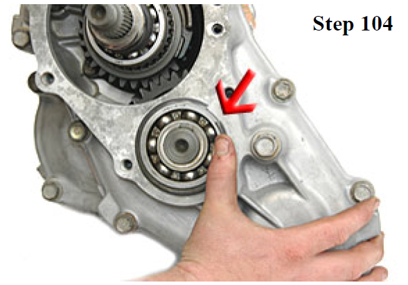
104. Install the outer snap ring on the idler bearing.
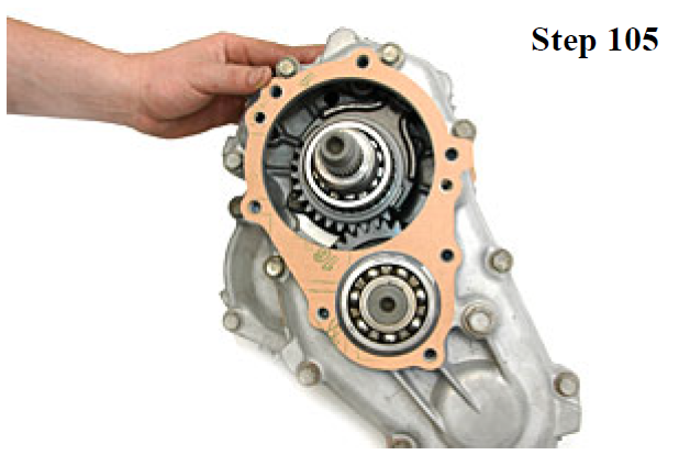
105. Place the new paper gasket onto the back of housing #3.
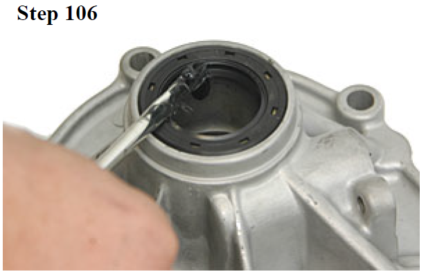
106. Remove the old output seal on housing #4. Install the new seal and apply grease to the inner lip.
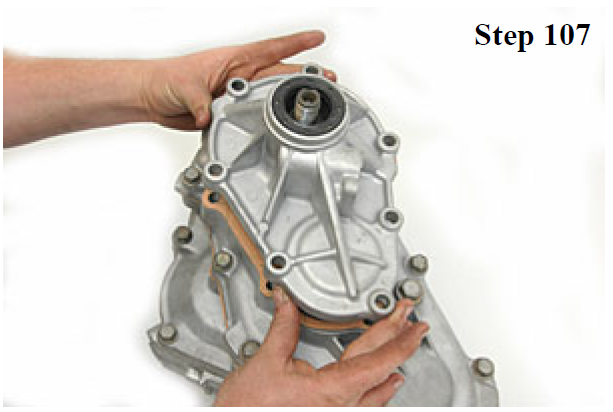
107. Install housing #4 onto the back of housing #3. Install 7 bolts into housing #4. Torque to 30 ft/lbs.
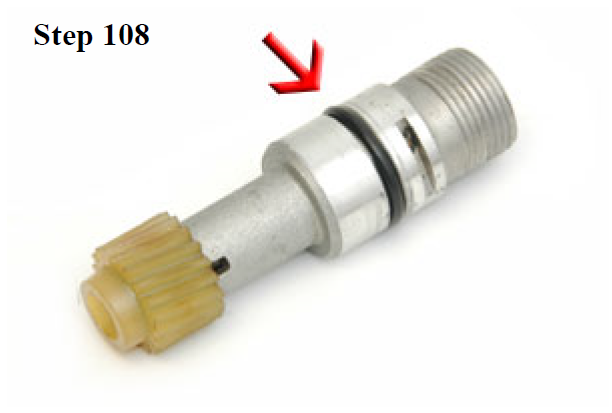
108. Using a screwdriver, remove and replace the speedometer sender seal. Apply grease to the plastic speedometer drive gear.
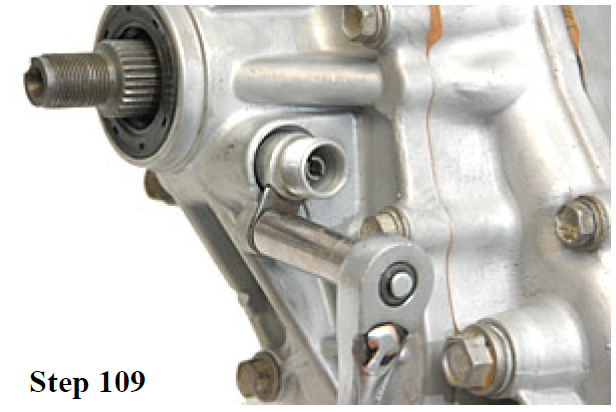
109. Slide the speedometer sender into housing #4. Install the speedometer lock tab and bolt, torque to 10 ft/lbs.
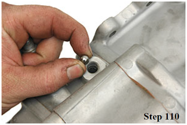
110. Rotate the case so it is on it's side. Drop in one detent ball.
111. Next drop in one detent spring.

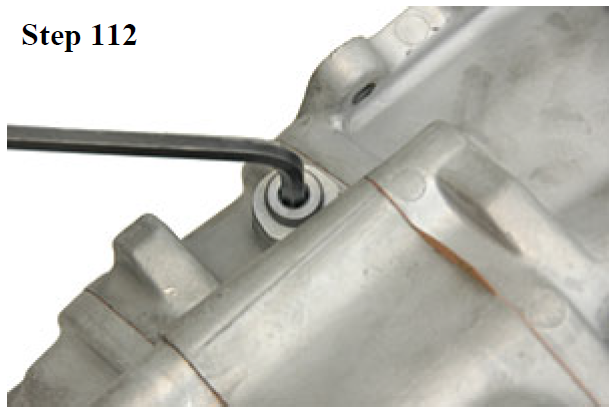
112. Apply a small amount of silicon to the threads of the detent plug and install. Flip the case over onto the other side and install the ball, spring and plug as above.
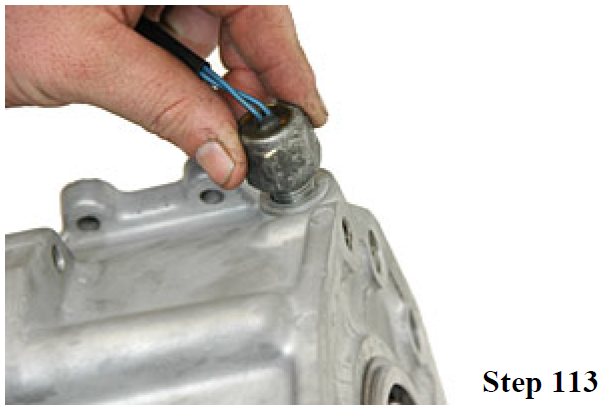
113. Install the 4wd shift light switch into housing #1.
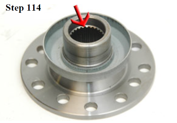
114. Apply Permatex® Ultra Grey® silicon to the inside splines of both flanges. Slide the flanges into place on the transfer case.
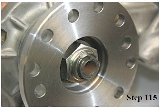
115. Install the main shaft nuts and washers. Tighten each nut to 90 ft/lbs. Using a punch, stake the nuts into the main shaft as shown.
Transfer Case Oil:
After installing the transfer case, remove the rear fill plug and fill with 80/90W GL5 gear oil. Once oil starts leaking out of the fill hole, the transfer case is full. The transfer case oil level should be checked after 10 miles of driving and topped off as necessary. Conventional or synthetic oil may be used.
Transfer Case Oil Service Recommendations:
After any major internal work to the transfer case, we recommend that the oil be changed after the first 1,000 miles or after the first trail ride (which ever comes first) to remove debris suspended in the oil. After the initial change, the oil should be change once each year or each 10,000 miles which ever comes first. The fluid level in the case should also be checked each time the engine oil is changed. The fluid level should be checked after a roll-over as it is possible for fluid to leak out of the transfer case when the truck is on its side or is inverted.