


Adjustable Cam Gear
(Dual Row Chain)
Adjustable Cam Gears are the only way to change cam timing on 20R, 22R, 2RZ, and 3RZ series Toyota motors and still be accurate. Both single and double adjustable camshaft gears are available from LC Engineering. Adjustable cam gears are generally used to correct camshaft timing after the head has been milled or when the block is decked. Cam gears are an effective way to dial-in a camshaft by advancing the cam for low-end power or retarding the cam for top-end power.
Adjustable cam gears can be used with mechanical fuel pumps by modifying the pump arm to clear the gear locking nuts and utilizing our Modified Mechanical Fuel Pump Eccentric, see Part #: 1021028. If swapping from Mechanical to an electric fuel pump, you must use a distributor drive gear spacer in place of the Eccentric, see Part #: 1081025. These spacers are found on most 22RE/RET stock engines since they use electric fuel pumps.
This product should not be used in a manner that violates Federal EPA Laws.
Check out LCEngineering.com for New Products, Tech Articles, Specials & Monthly Newsletters!
| Note: Images are for illustration purposes only. Images may not represent the product listed. Please contact customer service with any questions or concerns: 1-928-505-2501. |
- 1975-1980 20R 2.2L Engines
- 1981-1995 22R 2.4L Engines (w/ dual row timing chain)
- 1983-1995 22RE 2.4L Engines (w/ dual row timing chain)
- 1985-1988 22RET 2.4L Engines (w/ dual row timing chain conversion kit)
To open a printable PDF version of this instruction CLICK HERE
Thank you for purchasing an adjustable cam gear from LC Engineering!! This adjustable gear is the only way to accurately adjust your cam timing and gain the most potential from your engine. LC Engineering always recommends using an electric fuel pump whenever possible but if you have a mechanical fuel pump then you will need to trim the bolts on the adjustable cam gear down flush with the nut. If you don't trim them down they will interfere with the fuel pump arm and cause engine damage. You will also need to modify your fuel pump eccentric to accommodate your new adjustable cam gear or LC Engineering can supply you with a fuel pump eccentric that has already been modified (part #1021028).
NOTE: If you remove the fuel pump eccentric you must use a distributor drive gear spacer (part #1081025). These spacers are found on most 22RE/RET engines since they use electric fuel pumps.
Camshaft Degreeing Procedures:
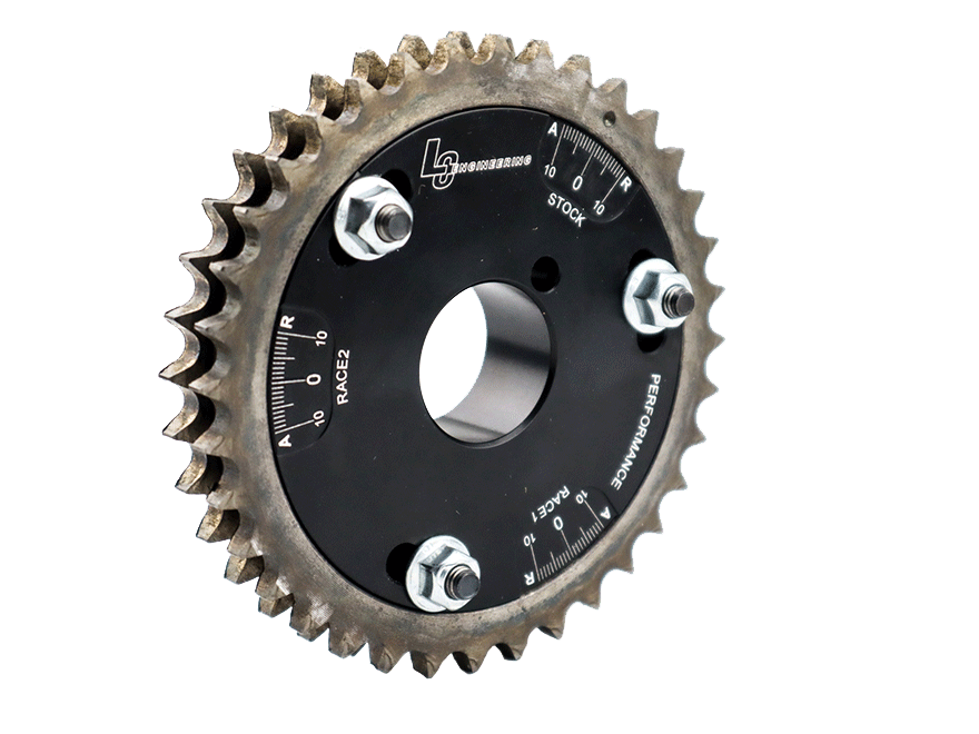
You will notice on your new adjustable cam gear that there are 3 separate sets of degree marks. There is a "STOCK", a "RACE 1" and a "RACE 2" (see pic). The "STOCK" degree marks are based on a stock, non-adjustable cam gear. Because of the numerous variations in engines; including head decking, block decking, camshaft size etc... there is no way to know exactly where your specific engines cam timing true "0" is at. LC Engineering always recommends that you degree your camshaft in with the new gear so that you can find the true "0" on your engines. If this is not an option for you then LC Engineering has come up with an alternate method that will work but is not nearly as accurate. Read through both the "Basic" and "Advanced" installation guidelines below to determine which method you will use.
Basic Camshaft Gear Installation (less accurate method):
If you line up the "0" from the "STOCK" set of marks with the line scribed in the outer gear, your new adjustable gear will match the stock gear exactly. You can then adjust the cam timing accordingly.
- Advancing the cam timing (turning cam so the outer gear line moves towards the "A" on the hub) will move the power band lower in the RPM range.
- Retarding the cam timing (turning cam so the outer gear line moves towards the "R" on the hub) will move the power bandhigher in the RPM range.
When a cylinder head or block has been decked or re surfaced your stock cam timing will be retarded. That means you will want to advance the timing to get it back to where it was originally.
Advanced Camshaft Gear Installation (recommended method):
We recommend the Intake Lobe Center Method to degree the camshaft. This will achieve the most accurate settings available,resulting in the best performance from your engine package. The new versions of the cam gear have 2 separate "RACE" settings for different set-ups. This will allow you to log different cam timing adjustments in each set of marks for different race tracks or vehicle set-ups.
Finding True Top Dead Center (TDC):
- The first step is to Install the degree wheel on the crankshaft, then make a pointer for the degree wheel using a stiff piece of wire, such as a metal coat hanger. Loop the opposite end of the wire onto one of the engine bolts (usually you can use a timing cover or water pump bolt).
- Remove all spark plugs to make it easier to turn the engine by hand.
- Rotate the crankshaft to approximate TDC on the #1 cylinder, compression stroke. The camshaft dowel pin will be in the 12 O'clock position.
- Adjust your fabricated pointer to the "0" mark on the degree wheel.
- Rotate the engine by hand (not using the starter) 90º. Remove #1 cylinder spark plug.
- Adjust your piston stop so that the bottom of the stop is exactly 2" from the spark plug seat part of the stop. This is very important; if you adjust it too far down it can damage your valves and/or piston.
- Rotate the engine (by hand) counterclockwise until the piston contacts the piston stop. Mark and record the number that the pointer is at on the degree wheel.
- Rotate the engine (by hand) clockwise until the piston contacts the piston stop. Mark and record the number that the pointer is at on the degree wheel.
- Add the 2 recorded numbers together and divide the answer by 2. Record that answer.
- The answer from the previous step will be where your pointer will go now. For example: If you get 11º after top dead center
(left side of "0" on degree wheel) and then you get 5º before top dead center (right side of "0" on degree wheel). You will add 11º + 5º = 16º. Then 16º ÷ 2 = 8º. You will now adjust your pointer to point at the 8º mark before top dead center (right side of degree wheel). - Recheck TDC by rotating the engine (by hand) counterclockwise until the piston contacts the piston stop. Record the number that the pointer is at on the degree wheel.
- Rotate the engine (by hand) clockwise until the piston contacts the piston stop. Record the number that the pointer is at on the degree wheel.
- The numbers recorded this time around should be the same. If not readjust the pointer and recheck TDC. For example: If you use the same example from step #9 your pointer should be at 8º on both sides of "0"
- Once you have found true TDC remove the piston stop from cylinder head.
- Install a dial indicator (with magnetic base and fixture plate). Position the indicator on the #1 intake valve retainer so that the dial indicator shaft will travel parallel to the valve.
Cam Card Specifications:
Review the cam card provided with your camshaft. Find the intake center line the cam was ground on. If not provided you can compute the center line by adding the intake opening degrees at .050" valve lift to the intake close degrees at 050" valve lift plus 180º crank rotation. Divide this number by 2 and subtract the smaller number. This is your intake center line of the cam you are about to degree. Check every cam, they will differ from cam to cam.
Example:
Opens 13º + Closes 37° + 180° = 230°
230° ÷ 2 = 115°
115° - 13° = 102° Lobe Center
NOTE: Always rotate the crankshaft in the running rotation (clockwise looking at the front of the engine). Never reverse crankshaft rotation to achieve a reading when degreeing the camshaft.
Step 1: Find Valve Open @ .050" Lift: With your indicator on the retainer and the rocker set at zero lash on the base circle, zero the dial indicator. Rotate the crank until the indicator reads .050" valve lift off base circle. Read the degree wheel and record. Example would be 11º on the degree wheel BTDC.
Step 2: Find Valve Closes @ .050" Lift: Rotate the crankshaft until the dial indicator reads .050" off the base circle (valve closing). Read the degree wheel and record. Example 39° on the degree wheel ABDC.
Step 3: Calculate Lobe Center: To figure the exact lobe center add intake open number and intake close number plus 180º. Divide
this total by 2 and subtract the smaller number (usually the intake open number).
Example:
Intake open 11° + Intake close 39° + 180° = 230°
230° Duration ÷ 2 = 115°
115° - 11° = 104° Lobe Center
In our example your cam is currently set to a 104° Lobe Center. Compare your actual findings with the information from your cam card and adjust the cam accordingly.
Step 4: Adjusting The Camshaft: Loosen the three 10mm lock nuts on the cam gear. Advance or retard the gear to achieve the proper intake center line for your specific cam. Torque the nuts to 8ft.-lb. And recheck your numbers to assure a proper setting. Once indexed correctly, using a sharp small chisel, align with the zero mark on the gear hub and make a reference mark on the outer gear for future reference. You have now completed the degreeing process.
Calculating Duration. To calculate duration at .050" valve lift . Add the degrees when the valve opens @ .050" to the degrees the valve closes @ .050" plus 180°.
Example:
Opens 11º + Closes 39º + 180º = 230º Duration @ .050" Valve Lift
Performance Tips:
To change the performance of your engine, you can advance the cam to achieve a lower RPM torque curve (bottom end power) or retard the cam to achieve a higher RPM torque curve (top end power). Make small adjustments and record your results. This way you can always refer back to your previous settings. Ignition timing and cam timing are not the same. Since the distributor is turned by the camshaft, always recheck your ignition timing after adjusting the cam timing.
21 Reviews Hide Reviews Show Reviews
-
Another great buying experiance
Hi I run a busy engine shop in Australia. Discovered LCE through a friend Everything we have purchased has been top quality and the communication and shipping has been fast a trouble free. Thanks guys for a great product & experience John Pilla PowerHouse Engines
-
Awesome!
Exactly what I wanted and it was shipped to my house quick! Thanks LCE
-
adjustable cam gear
top quality cam gear.
-
Dual row adjustable cam gear
I recieved the gear within 2 days ground post! Everything came bagged and with clear instructions, the gear itself looked so good, I hated to cover it up with the valve cover! Fit and finsh like factory. Facebook Toyota mini truck group approved!
-
owner
Great , Very professionalGreat ,Very professionalGreat , Very professional..So far every phone call has been handled I believe perfect , the people at LC are with a doubt people that know what they are doing and know there product . Every part I ordered is exactly what I wanted . PS ...THANKS to the techs the parts ordered and installed my power is better and my gas mileage went from 18 miles per gal to 22.4 miles per gal..OK I am a happy customer
-
Moving power band around .
I love how easy this was to install and adjust . Also how it uses factory metal . So I know it will most likely last as long as my 22re . I run LC Engineering dual chain kit on my lazer block and this install was fast and easy. I can adjust my power level from being a torque monster down at low rpm to running a little stronger above 3k rpm. Really is nice when I go crawling I just adjust it one way and when I want hi way power for long trip I can adjust it for the use that I do. I also can set it and forget it . This is very effective I like it! Great price!
-
Dual row cam gear
Great product. Fits great. Now I can get my hybrid into the powerband it was built for.
-
Adjustable Cam Gear for Dual Row Chain
Great product. I will recommend this product to all my friends.
-
excellent part
Great part.


")