

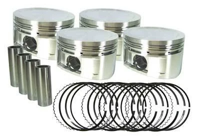
2RZ Pro Forged Piston Set | 10.0:1 Compression (+.040")
The Ultimate High-RPM Upgrade for Toyota 4-Cylinders
Stop worrying about ring land failure or piston fatigue. Pulling from a decade of performance metrics gathered on our signature 20R, 22R, and 22RE big-bore setups, this forged aluminum piston kit brings uncompromising strength to the Toyota 2RZ and 3RZ platforms.
Kit Includes
- Premium Forged Aluminum Pistons (+.040)
- Tool-Steel Chromoly Pins (Lightweight)
- High-Strength Spiral Locks
- Pro Performance Ring Pack
Specifications
- Bore Size: +.040" Overbore (93mm/94mm big bore options available)
- Target Compression: 10.0:1. Engineered explicitly for high-compression, naturally aspirated setups or mild forced-induction applications demanding responsive power and reliability.
- Material Integrity: Forged structural makeup provides the mechanical toughness required to handle violent cylinder pressures and extreme thermal loads that crush factory cast components.
Installation & Valve Relief Notes
- Camshaft Compatibility: Custom valve relief machining is highly recommended for high-lift or aggressive aftermarket camshaft profiles. See our Notch Labor service to configure this option and safeguard your valve-to-piston clearance.
- Bore & Hone: Precision block prep is mandatory. Ensure your cylinder walls are machined to the precise specifications required for high-performance forged alloys, and always deliver the piston set to your engine builder prior to final honing.
| Note: Images are for illustration purposes only. Images may not represent the product listed. Please contact customer service with any questions or concerns: 1-928-505-2501. |
- 1995.5-2004 2RZ 2.4L Engines
CP Piston Ring Honing Specifications
Critical Block Preparation for Optimal Ring Sealing
For maximum performance, proper cylinder prep is mandatory. When installing our premium CPN or CPN2 or piston ring sets, the cylinder walls must be precision-finished to ensure immediate seat-in and long-term durability.
Machining Requirements
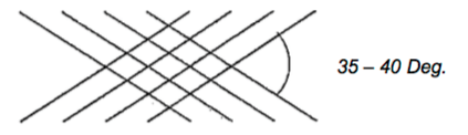
- Honing Requirements: Plateau Honed
- Cross-Hatch Angle: Finished strictly between 35-40 degrees.
- Note: To achieve the exact surface finish required for high performance forced alloy rings, always deliver this specification sheet and your piston ring pack to your automotive machinist prior to final block honing.
Cylinder Honing & Surface Finish Guidelines
Achieving the Target Surface Roughness
For proper ring seating and optimal cylinder wall lubrication, honing manufacturers recommend specific grit ranges depending on your abrasive type. These guidelines apply to standard gray cast iron engine blocks as well as Nikasil-coated cylinders.
Initial Honing Specifications
- Conventional Stones: Use #220-#280 grit
- Diamond Stones: Use #325-#550 grit
Final Plateau Finishing
After completing the initial hone with either conventional or diamond stones, a final finishing step is mandatory to create a true plateau surface. This process removes jagged peaks, folded metal, and torn material left behind by the coarser stones.
- Abrasive Method: Finish by smoothing the cylinder surface with a fine-grit conventional abrasive (#400-#600 grit).
- Brush Method: Alternatively, sweep the bores using a flexible brush or a specialized nylon-bristle plateau honing tool.
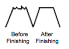
- Critical Verification Note: Before finalizing your block preparation, always consult with your honing equipment manufacturer. Verify that the recommended stone grit ranges will precisely achieve the following target surface finishes:
- Rz (Average Roughness Depth): 59-138 μin (1.5 - 3.5 μm)
- Ra (Roughness Average): 15-35 μin (0.4 - 0.9 μm)
CP Piston Ring Gap & Installation Guidelines
Failure to verify and set the correct piston ring end gap can result in catastrophic engine failure. While the calculations below provide industry-standard baselines, the ideal ring gap varies based on your specific engine configuration and application. Increased clearances are mandatory for forced induction, nitrous oxide, filled blocks, endurance racing, and other extreme environments. Final verification and suitability remain the absolute responsibility of the engine builder.
For dedicated technical support or application-specific questions, please contact CP directly at 949-567-9000.
Determining Target Ring Gap
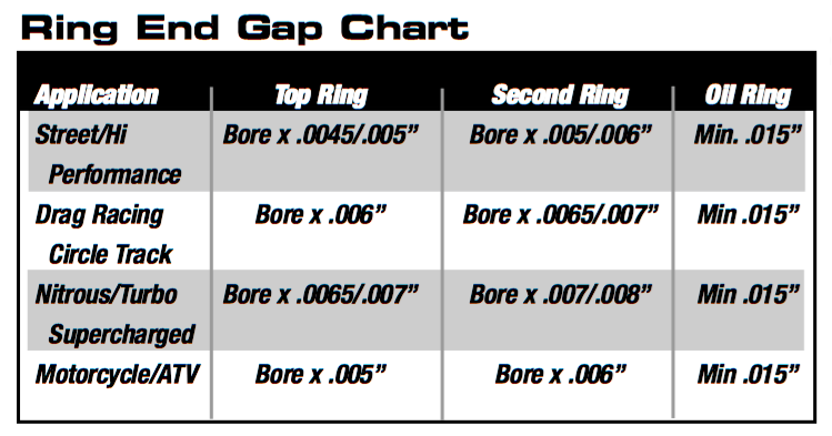
To calculate your required ring end gap, locate your specific application multiplier in the technical reference table.
- Important: All cylinder bore measurements must be converted from millimeters to inches before applying the multiplier formula.
Mathematical Conversion Formula
- Cylinder Bore (mm) divided by 25.4 = Cylinder Bore (Inches)
- Cylinder Bore (Inches) x Application Multiplier = Required Ring E
Calculation Example (Street Application Baseline):
- (Metric to Standard): 81mm divided by 25.4 = 3.189 in.
- (Apply Multiplier): 3.189 in. x 0.005 = 0.016 in. target top ring end gap
Premium Ring Installation Specifications
Critical Alignment & Clearance Guidelines
For maximum performance and immediate break-in, proper cylinder preparation and layout verification are mandatory. While the enclosed technical charts provide industry-standard baselines, highly specialized or extreme applications may demand custom clearances.
Always thoroughly review the accompanying diagrams and specifications prior to final assembly to ensure precise piston-to-ring tolerances.
Step-by-Step Measuring Process
- Torque Plate Installation if applicable to your specific engine blueprint, a torque plate must be installed on the engine block and torqued strictly to factory or fastener manufacturer specifications. This simulates true cylinder distortion under standard operating loads.
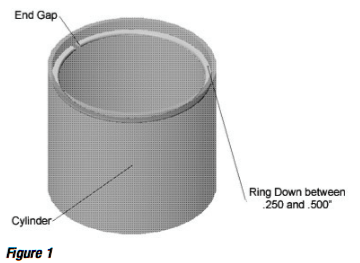
- Ring Squareness & Positioning Insert the piston ring into the cylinder bore. The ring must be positioned below the deck surface and squared perfectly to the bore axis. (Refer to Figure 1)
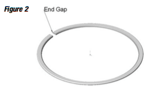
- Measuring Clearances carefully measure the exact ring end gap using a precision feeler gauge or an equivalent specialized measuring instrument. (Refer to Figure 2)
- Tip: Use an upside-down piston without rings to push the ring down evenly into the bore.
- Note: Record each measurement per cylinder and verify that the final gap meets your specific application multiplier requirements before moving to the next cylinder.
Ring Filing Procedures
When adjusting your ring end gap to match your engine blueprint specifications, follow these strict mechanical guidelines
- Use the Right Equipment: Always use a dedicated piston ring filing tool. Never use standard hand files or grinders.
- Filing Direction: File the ring end in a strict inward direction (from the outside face toward the inside diameter) to prevent chipping or peeling the outer high-performance coating or plating.
- Maintain Squareness: Ensure the ring faces remain perfectly square and flat to the sides of the filing tool during the entire process. Deburr the filed edges lightly with a fine sharpening stone before checking clearances.
- Technical Bore Variance Note: Ring sets are precision-manufactured to fit specific nominal bore sizes. For every 0.001 in. the cylinder bore measures over its intended size, your ring gap will automatically increase by 0.00314 in. Factor this geometric variance into your final gap calculations.
Top Ring Orientation & Installation
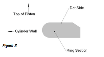
Correct vertical orientation ensures proper gas sealing and thermal transfer. Inspect the top compression ring closely and install based on the following physical characteristics:
- Marked Rings: If the ring features a laser-etched dot, number, or manufacturer writing, always install the ring with this marked side facing up (toward the cylinder head).
- Beveled Rings (Unmarked): If the ring is unmarked but features an inner ID bevel, it must be installed with the bevel side facing up.
- Symmetrical Rings: If the ring has no dots, writing, or inner bevels, it is completely symmetrical and can be installed with either side facing up.
Critical Layout & Directional Protocol
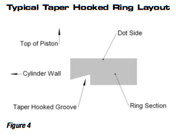
The second compression ring (scraper ring) plays a critical role in oil and secondary pressure sealing. Incorrect vertical orientation will cause excessive oil consumption and engine smoking. Inspect the second ring closely and install based on the following physical characteristics.
- Marked Rings: If the ring features a laser-etched dot, number, or manufacturer mark, always install it with the marked side facing up (toward the cylinder head).
- Taper Hook Groove (Scraper) Rings: If the ring features a taper hook groove profile, the sharp step/groove must always face down (toward the oil pan). (Refer to Figure 4)
- Symmetrical Rings: If the ring is completely smooth and features no markings, dots, grooves, or inner bevels, it is fully symmetrical and can be installed with either side facing up.
Oil Ring Assembly & Installation Procedure
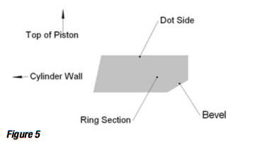
The oil ring assembly is responsible for scraping excess oil from the cylinder walls. Improper installation or modified components will cause immediate oil control failure and catastrophic cylinder wall scoring. Treat these delicate components with precision.
Three-Piece Assembly Layout
The vast majority of CP high-performance oil ring sets utilize a specialized three-piece architecture consisting of:
- Two Steel Rails: One upper rail and one lower rail that physically contact the cylinder wall.
- One Expander Ring: A central corrugated spring designed to provide uniform radial tension against the outer rails.
Clearance & Modification Guidelines
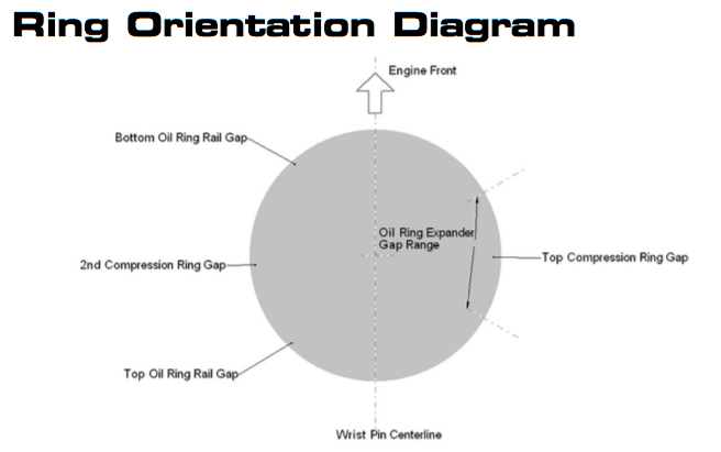
- Minimum Rail End Gap: Prior to final insertion, check the end gap of both the upper and lower steel rails inside the cylinder bore. The end gap must never be less than 0.015 in.
- Rail Alignment Warning: Ensure the ends of the rails butt cleanly against each other when compressed. They must never overlap or ride up over one another, as this will lock the ring pack and crack the piston ring lands.
- Expander Care: Do not modify, cut, trim or file the expander ring under any circumstances. It must remain entirely factory-original to maintain proper tension. When installing the expander, ensure its wire-inserted ends butt together perfectly rather than overlapping.
Disclaimer & Limited Warranty Policy
Critical Liability & Legal Notice
Due to the extreme stresses and unpredictable environments inherent to high-performance, racing, and motorsport applications, all CP Pistons/Pankl products and services are sold strictly "As Is" and "With All Faults." By purchasing or utilizing these products, the buyer explicitly understands, acknowledges, and agrees to the following legal terms as a core condition of doing business with CP Pistons/Pankl:
- No Express or Implied Warranties: CP Pistons/Pankl explicitly disclaims all warranties, whether express or implied, including but not limited to any implied warranties of merchantability, durability, or fitness or a particular purpose or application.
- Inspection Opportunity: The purchaser is provided a full, complete, and unrestricted opportunity to examine all parts, physical inventory, and associated technical specifications prior to purchase and final engine assembly.
- Exclusion of Damages: Under no circumstances shall CP pistons/Pankl be held liable for any special, incidental, punitive, or consequential damages. This strict exclusion includes-but is not limited to-the following:
- Damage to or loss of other property, engine components, or support equipment.
- Loss of profits, business revenue, or operational uptime.
- Costs associated with purchasing replacement goods or secondary labor.
- Independent claims made by the purchaser's own clients or third-party customers resulting directly or indirectly from the sale, installation, or mechanical use of these components.


