
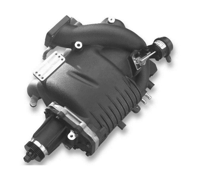
Magnuson 3.4L Supercharger System
Give your classic Toyota truck or SUV the substantial power upgrade it deserves with the Magnuson TVS1320 Supercharger System. Engineered specifically for the legendary 334L 5VS-FE V6 engine, this premium, direct bolt-on system delivers a massive 42% increase in horsepower and an additional 23% more torque over factory specs. That elevates your output to an incredible 262 HP and 263 lb-ft of torque at the crank, completely transforming your vehicle's towing, mountain climbing, and highway acceleration.
Advanced Eaton TVS Technology & Efficiency
- At the heart of this system is Eaton's advanced Twin Vortices Series (TVS) technology, featuring a positive-displacement design with high-helix, four-lobe rotors. This setup provides a 30% larger displacement volume than the older MP62 supercharger units, offering maximum thermal and volumetric efficiency across the entire RPM range.
- Power delivery is instantaneous with zero lag, providing a smooth, linear torque curve exactly when you need it. To maximize fuel economy, an integrated vacuum bypass system automatically unloads the supercharger during engine idle and part-throttle cruising conditions, resulting in virtually no parasitic drag when extra power isn't required.
Turnkey Reliability & Seamless OEM Fitment
- Designed for long-term durability and minimal downtime, this complete package features an integrated intake manifold and supercharger housing cast together as a single unit. This smart engineering eliminates potential gasket leaks and ensures a highly compact, leak-proof layout with an attractive OEM look, fit, and finish.
- The system is engineered to run safely on your vehicle's stock engine calibration, requiring no complex ECU flashes. Best of all, the supercharger housing arrives pre-filled and completely sealed for a lifetime of maintenance-free operation-eliminating external oil coolers, lines, or routine fluid changes. Installation is straightforward and can be completed over a weekend by a competent enthusiast with basic hand tools, or in about a day by an experienced mechanic.
Key Product Features
- Substantial Power Gains: Delivers a 42% increase in HP (262 HP) and a 23% increase in torque (263 lb-ft) at the crank.
- Instantaneous Throttle Response: Advanced Eaton TVS four-lobe rotor design ensures immediate low-end grunt with zero turbo lag.
- Smart Fuel Efficiency: Integrated vacuum bypass system unloads the blower during cruising to minimize parasitic drag and protect fuel economy.
- Stock Tune Compatible: Engineered to safely utilize the vehicle's factory ECU calibration for immediate plug-and-play operation.
- Maintenance-Free Longevity: Fully self-contained, sealed unit requires no oil changes or external fluid reservoirs.
- Streamlined Single-Cast Assembly: Combines the intake manifold and supercharger housing to eliminate potential vacuum or boost leak points.
- Emissions Compliant: 50-State Smog Legal under CARB EO# D-488-57.
- Manufacturer Backed: Includes a standard 3-year/36,000-mile limited supercharger system warranty.
Boost Variance Disclosure
Please note that final registered boost levels are dependent on external variables and environmental conditions. Actual boost pressure will vary depending on ambient air temperatures, atmospheric humidity, mechanical health, and local elevation.
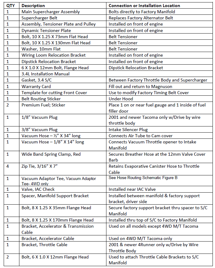
Kit Includes
- (1) Fully Integrated Cast Aluminum Intake Manifold & TVS1320 Supercharger Assembly
- (1) Complete Set of Premium Installation Hardware, Brackets, and Pulleys.
- (1) High-Quality Replacement Drive Belt
- (1) Detailed, Step-by-Step Installation Manual with Model-Specific Photographs
-Note: While engineered primarily for standard models, this system is compatible with other Toyota 5VZ-FE 3.4L V6 platforms. Please note that alternative or highly modified applications may require a custom calibration.
| Note: Images are for illustration purposes only. Images may not represent the product listed. Please contact customer service with any questions or concerns: 1-928-505-2501. |
- 1997-2004 Toyota Tacoma 3.4L V6
- 1996-2002 Toyota 4Runner 3.4L V6
- 1997-1998 Toyota T100 3.4L V6
- 2000-2003 Toyota Tundra 3.4L V6
CLICK HERE for a printable PDF version of these instructions.
Phase 1: Prepare Vehicle
1. Fuel Requirement
Before beginning the installation, ensure the vehicle's fuel tank has been completely run down and filled with premium 91 octane (or higher) fuel. Operating the supercharger on low-octane gasoline can cause severe engine knocking (pinging) and potential internal engine damage.
2. Engine Cleaning
Thoroughly clean the engine bay and the engine components prior to teardown. Removing accumulated grease, dirt, and debris prevents contaminants from accidentally falling into open intake ports or engine internals during the installation process.
3. Cool-Down Period
Ensure the engine is completely cool to the touch before starting any work. Working on a hot engine poses a severe risk if burns and can lead to the warping of hardware or components during removal.
4. Cable & Hose Documentation
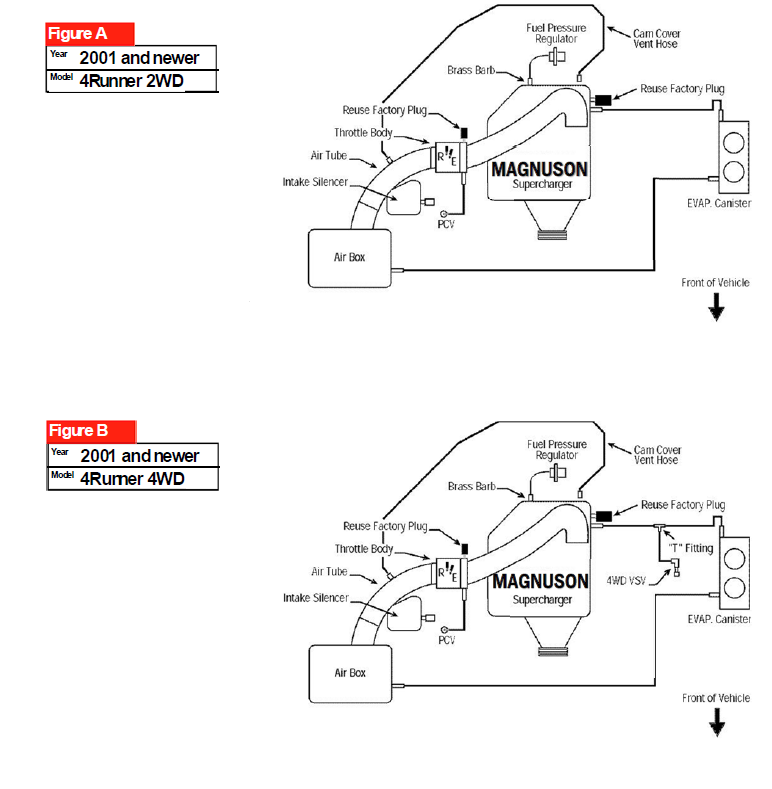
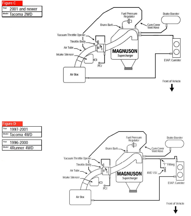
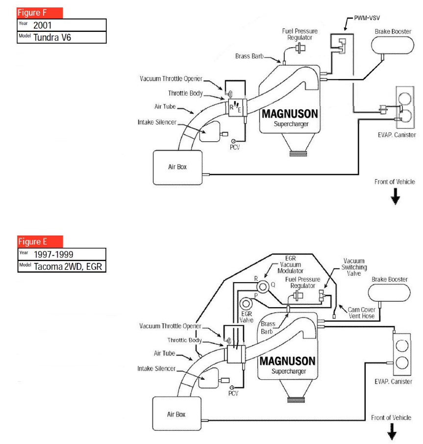
To simplify reassembly, it is highly recommended to take reference photographs or draw detailed diagrams of the factory cable and vacuum hose routing before disconnecting any lines. Note that while some factory vacuum connections will change o accommodate the supercharger layout, reference points remain helpful. Always verify final routing using the dedicated vacuum diagrams located at the back of this manual.
5. Hardware Organization
This supercharger system is engineered to reuse the majority of your factory nuts, bolts and fasteners. As you remove hardware, immediately label or store them alongside their corresponding factory components to ensure a seamless, organized, and efficient reinstallation.
Phase 2: Disassembly Instructions
1. Battery Disconnection
Disconnect the negative (ground) battery cable from the battery terminal. This eliminates the risk of accidental electrical shorts or component damage during the teardown process.
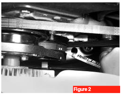
2. Drive Belt Marking
Using tape or a permanent marker, clearly mark the forward edge and direction of rotation on both the power steering and air conditioning compressor drive belts (See Figure 2). Reusing a belt in the opposite direction of its original rotation can cause premature wear and fraying. Ensuring the belts are reinstalled in their exact original positions protects their structural integrity.
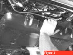
3. Gravel Guard Removal
If equipped, remove the factory gravel guard from underneath the radiator assembly (See Figure 3). Removing this panel provides the necessary clearance to access and service the air conditioning belt tension adjuster.
- Pro Tip: Although the factory gravel guard consists of two separate pieces, it is significantly easier to remove and reinstall the entire component as a single, fully assembled unit.
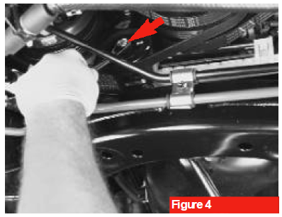
4. A/C Belt Loosening
Loosen the pinch nut located in the center of the air conditioning (A/C) compressor idler pulley. Next, back off the adjuster bolt sufficiently to relieve tension and loosen the belt. (see arrow, Figure 4).
5. Power Steering Pump Loosening
Using an angled flat ratchet for proper clearance, loosen both the pinch nut and the adjuster bolt on the power steering pump assembly to relieve belt tension.
6. Accessory Belt Removal
Carefully remove the loosened power steering and A/C compressor drive belts from their respective pulleys and set them aside.
7. Alternator Belt Removal
Loosen the top alternator pivot bolt, the pinch nut, and the adjusting bolt to slacken the alternator drive belt, then remove it. Note that this factory belt will not be reused; it will be replaced by a new, premium drive belt supplied directly in the supercharger kit.
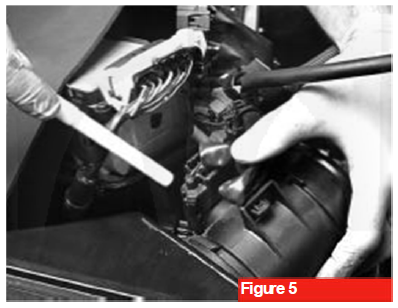
8. Air Intake & MAF Sensor Disconnect
Loosen the factory air intake tube clamps at the throttle body. Carefully disconnect the electrical plug from the Mass Air Flow (MAF) sensor.
- Note: The MAF Sensor element (see pointer, Figure 5) is extremely fragile. Exercise extreme care when working around or handling this component to avoid internal damage.
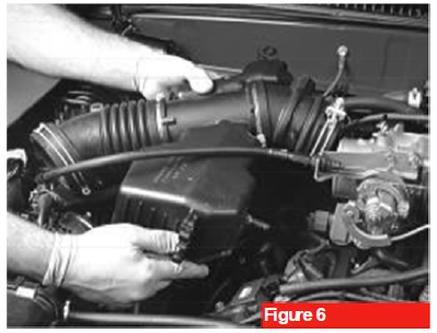
9. Air Intake Tube Removal
Disconnect any remaining vacuum or PCV line connections from the factory air intake tube, then completely remove the tube assembly from the engine bay (see Figure 6).
10. Vacuum Switching Valve (VSV) Inspection
Certain models are equipped with one or two Vacuum Switching Valve (VSV) assemblies. Consult the model-specific routing diagrams at the back of this manual to locate your specific configuration. If your VSV is factory-mounted to the rear of the engine, it must be unbolted and relocated to the vehicle firewall using the specialized bracket supplied in the kit.
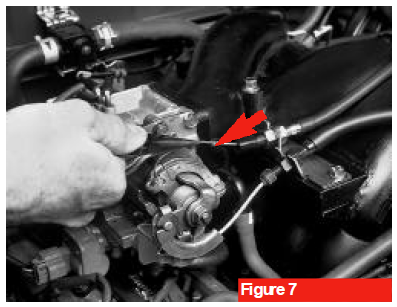
11. Throttle & Kickdown Cable Documentation
Carefully observe and note the current tension and slack adjustment of the factory throttle cable and, if equipped with an automatic transmission, the transmission throttle pressure (kickdown) cable. These exact adjustments must be replicated during the reassembly process.
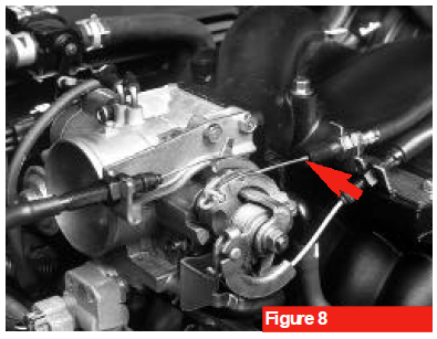
Automatic Transmission Reference: To establish a benchmark for proper reinstallation, locate the small metal crimp bead (the stake stopper) on the kickdown cable (see arrow, Figure 7). When correctly tensioned, this metal bead should sit perfectly flush with the outer edge of the cable's rubber boot/sheath (see arrow, Figure 8).
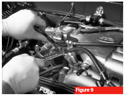
12. Cable Detachment
Loosen, but do not entirely remove, the adjustment nuts securing the cables to their mounting brackets (see Figure 9). Carefully slide the cables out of the bracket slots, then disconnect the cable ends from the throttle body linkage levers.
- Cruise Control Notice: If your vehicle is equipped with factory cruise control, do not disconnect or remove the cruise control cable from the throttle body linkage. Leaving it connected prevents the need for a tedious recalibration process later on.
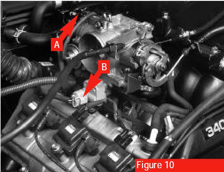
13. Sensor & IAC Valve Disconnect
Unplug the electrical connector from the Throttle Position Sensor (Marked as A) and the connector from the Idle Air Control (IAC) valve (marked as B) (see arrows, Figure 10).
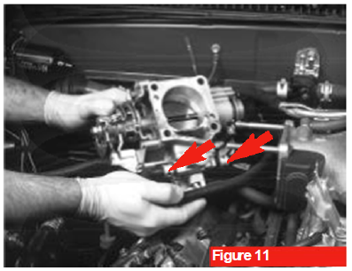
14. Vacuum Line Disconnection
Disconnect the vacuum lines from the throttle body assembly. Do not disconnect the two cooling system lines running to the unit (see Figure 11).
- Identification Note: The coolant hoses are secured by factory spring clamps (see arrows, pictured), whereas the vacuum hoses are push-on fitments and do not utilize clamps.
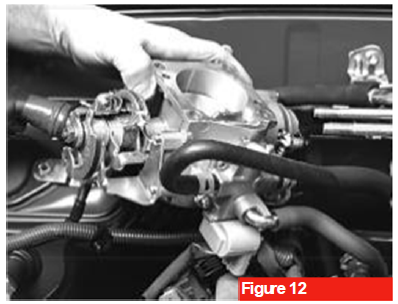
15. Throttle Body Displacement
Unbolt the throttle body and carefully lift it clear of the intake, keeping the coolant lines and cruise control cable (if equipped) attached. Gently move the entire assembly over to the passenger side of the engine by and secure it out of the way (see Figure 12).
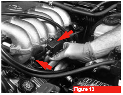
16. Driver's Side Bracket & Ground Detachment
On the driver's side of the engine, unclip the diagnostic data link connector from its mounting bracket (upper arrow, Figure 13) and set it aside. Next, remove the mounting bolt and the bracket that secures the diagnostic connector to the factory manifold; save this hardware and bracket for reassembly. Finally, remove the engine ground wire fastener and move the wire to the side (lower arrow, Figure 13).
17. Upper Manifold Vacuum Line Removal
Disconnect the heavy-duty vacuum hoses for the power brake booster, Positive Crankcase Ventilation (PCV) system, and Evaporative Emissions (EVAP) system from their respective hard-line tubes on the factory upper intake manifold.
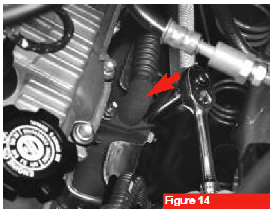
18. EGR Valve Inspection & Disassembly (Pre-2000 Models)
Early-model vehicles (pre-2000 Tacoma or T100) may be equipped with an Exhaust Gas Recirculation (EGR) valve. Inspect the driver's side exhaust manifold for the presence of the EGR transfer tube (see arrow, Figure 14). If equipped, unbolt and remove the valve assembly. Save all components, as the valve will be integrated back into the system later.
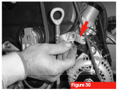
19. Intake Chamber Stay Disconnection
Remove the mounting bolt securing the upper intake manifold to the engine's structural intake chamber stay brace (see arrow, Figure 30). Retain this factory bolt for reassembly.
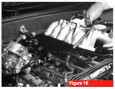
20. Upper Intake Manifold Removal
Unbolt and remove all remaining nuts and fasteners securing the upper section of the intake manifold plenum (surge tank), then carefully lift the upper assembly off the engine and set it aside (see Figure 15).
21. Lower Manifold Bracket Detachment
On the driver's side of the lower intake manifold, remove the two retaining bolts to free up the fuel return line mounting bracket; do not disconnect the actual rubber fuel line hose. Additionally, remove the single bolt securing the main engine wiring loom bracket to clear the work area.
22. Lower Manifold Fastener Removal
Remove the remaining securing bolts and nuts from the lower intake manifold runner section
- Hardware Extraction Tip: The factory nuts located at the far forward and rearward ends of the lower manifold will be reused. To prevent them from accidentally dropping down into the engine bay or open ports, extract them carefully using a magnetic retrieval tool.
23. Lower Manifold Extraction
Carefully lift and remove the lower intake manifold assembly from the cylinder heads (see Figure 16). Organize and save all factory nuts, washers, and the two short factory bolts, as they are required for the supercharger installation.4
24. Intake Gasket Inspection
Thoroughly inspect the factory intake runner gasket. If the gasket is entirely clean and free of tears, scoring, or compression deformation, it may be reused. If it shows signs of wear, discard it and replace it with a new factory replacement (Toyota PN:17176-62040).
- Gasket Interchangeability Note: The factory plenum gasket originally situated between the surge tank and the lower manifold (see Figure 15) is fully interchangeable and perfectly matches the mounting footprint required for the new supercharger intake manifold base.

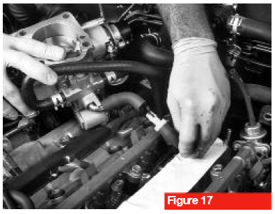
25. Cylinder Head Port Protection
Immediately cover or apply high-tack automotive masking tape over the exposed intake runner ports on the cylinder heads (see Figure 17). This critical step prevents any loose debris, hardware, or dust from accidentally entering the engine cylinders during the remainder of the modification process.
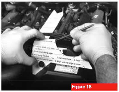
26. Timing Cover Marking
Position the provided alignment template onto the top section of the plastic timing belt cover. Using a scribe, paint pen, or permanent marker, carefully trace the outline of the template onto the cover to establish your cut lines (see Figure 18).
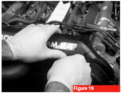
27. Timing Cover Clearance Trim
Safely route all electrical wiring and looms away from the immediate work area. Using a fine-tooth coping saw blade or flexible hand saw, carefully cut along your scribed mark (see Figure 19) and discard the trimmed plastic piece, This modification creates the necessary physical clearance required for the extended nose-drive housing of the supercharger.
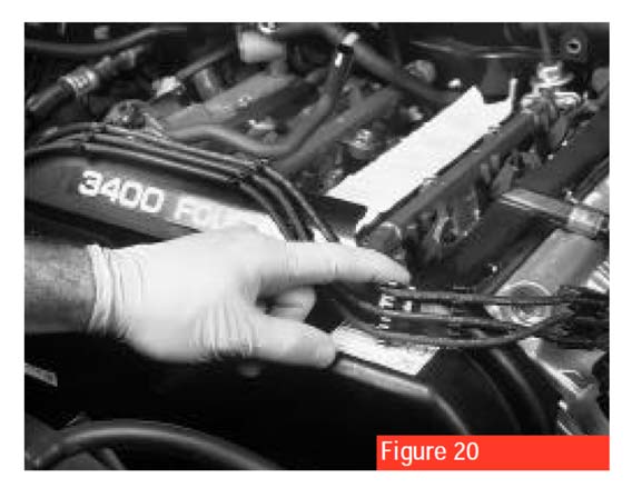
28. Edge Trim & Ignition Wire Routing
Install the provided split-plastic wire loom section over the newly cut edge of the plastic timing cover (see Figure 20) to protect the wiring from sharp edges. Ensure that the factory ignition wires are routed neatly underneath where the supercharger nose-drive housing will sit once installed.
Phase 3: Magnuson Dynamic Belt Tensioner Assembly Installation
1. Dipstick Removal
Remove the engine oil dipstick and carefully pull the dipstick tube out of the engine block to clear the front area of the engine.
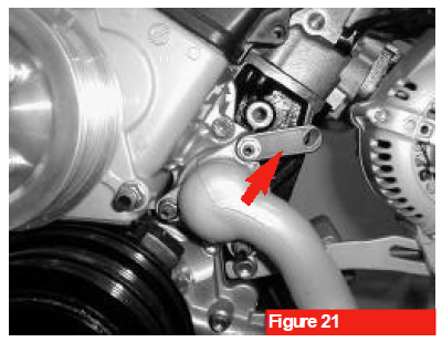
2. Wire Loom Relocation
Unclip the factory engine wire loom from its original metal mounting bracket. Install the provided wire loom relocation bracket onto the upper threaded stud of the water pump housing (see arrow, Figure 21), securing it with the original factory nut. Torque the nut to factory specifications, then clip the wire loom securely into the back of the newly installed relocation bracket.
3. Tensioner Plate Initial Alignment
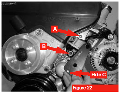
Position the dynamic belt tensioner plate onto the front of the engine block. Insert the supplied flat-head bolt (10 x 1.25 x 73mm) into Location A (see Figure 22). Thread the bolt in by hand, but do not fully tighten it at this stage.
4. Lower Mounting Bolt Alignment
Align the lower mounting hole of the belt tensioner plate with Location B on the block. Insert the second supplied bolt (10 x 1.25 x 130mm) through the lower hole to ensure perfect plate alignment.
Technical Note & Thread Maintenance
- Thread Cleaning: On high-mileage or heavily used vehicles, the factory threaded holes in the engine block (Arrows A & B in Figure 22) may have accumulated debris or corrosion. It is highly recommended to clean these holes with a thread chase or tap prior to bolt insertion.
- Threadlocker Application: To prevent loosening from engine vibration, apply a high-strength red thread-locking fluid (such as Loctite 262) to the threads of both the 10 x 1.25 x 73mm and 10 x 1.25 x 130mm fasteners before final installation.
5. Tensioner Plate Torque
Using a calibrated torque wrench, tighten the flat-head mounting bolt at Location A to final specification: 25 ft-lbs (34 Nm)
6. Alternator Positioning & Torque
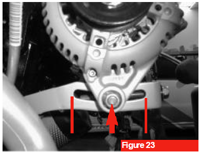
Remove the long alignment bolt previously inserted into Location B. Next, slide the alternator along its adjustable bracket until it rests at the exact midpoint of its travel range (see Figure 23). Secure the alternator in this position by tightening the top pivot bolt and to lower punch nut (see arrow) to factory torque specifications.
7. Dynamic Tensioner Placement
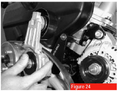
Position the dynamic belt tensioner assembly onto the mounting plate, ensuring that the new supercharger drive belt is routed properly behind the tensioner pulley (see Figure 24).
- Alignment Note: Ensure the locating stud on the backside of the dynamic tensioner housing slips cleanly onto the small alignment hole marked "C" on the belt tensioner plate (see Figure 22).
8. Tensioner Final Fastening
Insert the hex-head bolt (10 x 1.25 x 130mm) through the center of the dynamic tensioner and thread it into the mounting plate at Location B. Using a calibrated torque wrench, tighten this bolt to final specification. 40 ft-lbs (54 Nm).
Phase 4: Supercharger and Manifold Assembly Installation
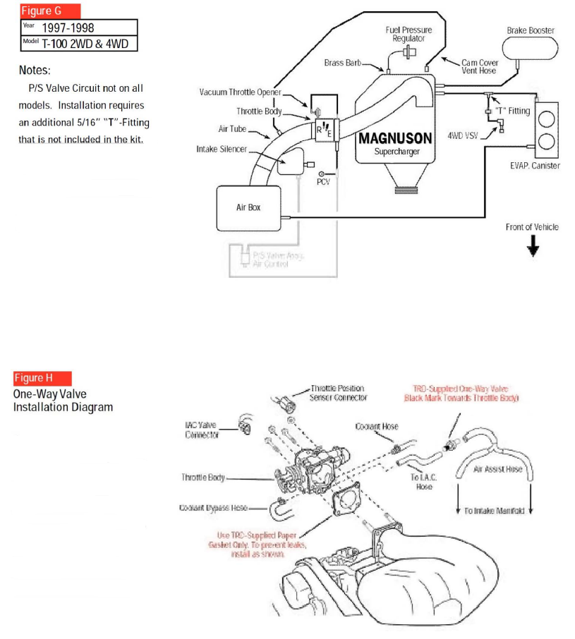
1. Inline One-Way Check Valve Installation
(Skip this step for 2001 and newer 4Runner models.)
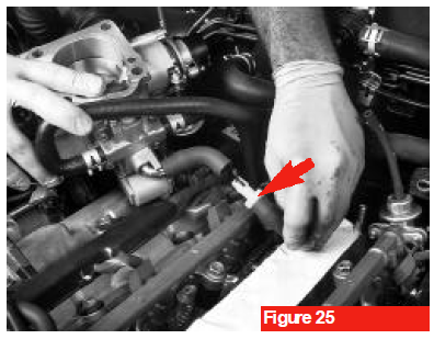
Locate the molded Idle Air Control (IAC) air hose and cut it at the straight section indicated in the manual (see Figure 25). Insert the provided inline one-way check valve directly into the cut section of the hose.
Critical Hose & Flow Identification
- Hose Verification: The IAC air hose and the engine coolant lines are a similar outer diameter. Ensure you do not cut a coolant line. The coolant lines are secured by factory spring clamps, whereas the IAC air hose is a push-on fitment without clamps.
- Valve Orientation: The check valve must be oriented so that air flows exclusively into the engine intake and blocks pressurized boost from escaping. If your valve features a black end, position the black side closest to the throttle body (see arrow, Figure 25). If your valve is a solid color, verify the correct orientation by gently blowing through it; install the valve so air passes freely toward the manifold side of the circuit.
2. Gasket Prep
Remove the protective masking tape from the cylinder head intake ports and thoroughly clean the mating surface. Reinstall the factory lower intake manifold gasket, ensuring it sits completely flush on the locating dowels.
3. Supercharger Drop-In Placement
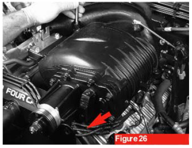
Carefully lower the combined supercharger and intake manifold assembly straight down onto the engine block. Verify that no loose vacuum lines, sensor connectors, or wire looms are trapped beneath the assembly. The factory ignition wires must be routed cleanly underneath the extended supercharger nose-drive housing (see arrow, Figure 26).
4. Bracket Alignment & Initial Mock-Up
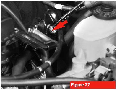
Once the manifold assembly sits perfectly flat against the cylinder heads, reinstall the factory driver's side manifold support brace bolt alongside the provided spacer (see arrow, Figure 27). Next, thread the two factory nuts onto the alignment studs located at the far forward and rearward ends of the lower manifold base. Use the provided M8 x 35mm hardware where applicable and hand-tighten all fasteners to secure the units alignment.
5. Manifold Fastener Torquing Sequence
Insert the supplied long manifold bolt (M8 x 1.25 x 170 mm) straight down through the upper supercharger housing into the lower manifold base, followed by the remaining two factory mounting bolts. Working in a crisscross pattern alternating from the center outward, torque all mounting bolts and the two end nuts to original factory specifications as outlined in your Toyota Repair Manual.
6. Secondary Accessory Belt Routing
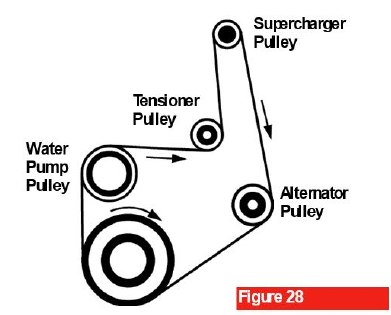
Route the factory accessory drive belt over the water pump pulley, the crankshaft pulley, and the alternator pulley (see Figure 28). Double-check that the belt ribs are perfectly aligned and completely seated within the corresponding grooves of each individual pulley.
7. Dynamic Tensioner Compression
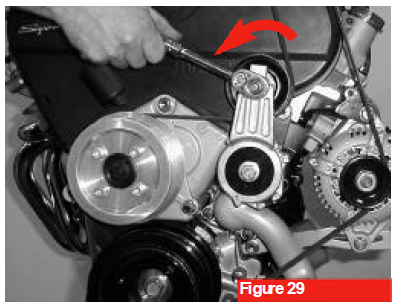
To facilitate the installation of the new supercharger drive belt, insert a 3/8" drive long-handle ratchet or breaker bar into the square drive recess on the dynamic tensioner arm (See figure 29). Firmly rotate the tool downward in the direction of the arrow to compress the internal spring, providing enough belt slack to slip the belt fully over the final pulley.
8. Accessory Belt Reinstallation
Reinstall the factory power steering and air conditioning (A/C) drive belts onto their respective pulleys. Ensure the belts are oriented in their original direction of rotation and aligned perfectly with the indexing marks you made during the disassembly phase (see Figure 2). Tension both belts to factory specifications.
9. Dipstick Relocation & Verification
Position the supplied dipstick relocation bracket onto the engine block (see arrow, Figure 30) and secure it using the factory mounting bolt. Carefully slide the factory dipstick tube back down into its mounting position, then fasten the tube to the new relocation bracket using the supplied small hex bolt (M6 x 1.0 x 12mm). Torque both bracket fasteners to 10 ft-lbs (14 Nm).
- Critical Seat Inspection: To prevent oil leaks, verify that the dipstick tube forms a perfect, pressurized seal where it enters the oil pan. Before final tightening, inspect the lower rubber O-ring/grommet at the base of the tube to ensure it is completely intact and fully seated into the engine block receptacle.
Phase 5: Throttle Body and Air Tube Installation
1. EGR System Reinstallation (If Equipped)
If your vehicle features a factory Exhaust Gas Recirculation (EGR) system that was removed during teardown, reinstall the valve assembly, transfer tubes, and hardware onto the exhaust and intake configurations at this time.
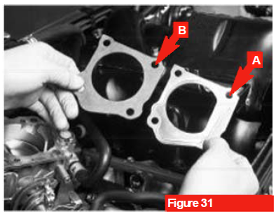
2. Throttle Body Integration & Gasket Selection
Position the throttle body onto the supercharger manifold inlet using the original equipment (OE) fasteners.
- Critical Gasket Notice: Do not reuse the factory OE metal gasket (marked as A in Figure 31). Reusing the factory metal gasket will cause an internal pressure bypass, reducing your supercharger's boost output by approximately 1.5 PSI. Instead, install the specialized composite gasket supplied directly in your kit (marked as B in Figure 31). Ensure the gasket is oriented correctly; its cutouts must perfectly match the footprint of the throttle body bore to avoid creating a severe vacuum leak.
3. Throttle Body Fastener Torque
Using a crisscross pattern, torque each throttle body mounting bolt to the exact specifications outlined in your Toyota Repair Manual. Do not over-tighten these fasteners, as doing so can warp the throttle body housing or strip the aluminum threads on the supercharger inlet.
4. Electrical Reconnection
- Plug the wiring harness connectors back into their respective terminals:
- Throttle Position Sensor (TPS) plug
- Idle Air Control: (IAC) valve connector
- Ignition Coil Plug (if disconnected during disassembly)
5. PCV Hose Connection
Route and attach the heavy-duty Positive Crankcase Ventilation (PCV) hose back onto the PCV valve located on the passenger-side valve cover. Ensure the fitment is snug to maintain proper crankcase pressure management.
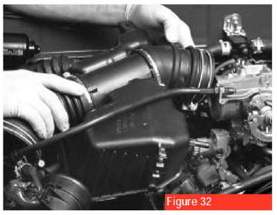
6. Intake Tube & MAF Sensor Assembly
Reinstall the main air intake inlet tube, securing it tightly to both the throttle body and the Mass Air Flow (MAF) sensor assembly using the factory clamps. Reattach all corresponding vacuum lines and breather tubes to their respective ports on the intake tract.
- Caution: Keep clear of the MAF sensor element (see Figure 32) during this step. The sensor is extremely sensitive to physical impact and contamination.
7. Throttle Cable Bracket Selection & Installation
Install the application-specific throttle cable bracket onto the top mounting bosses of the supercharger manifold. This kit includes three distinct brackets-select the correct variant fir your vehicle using the guide below.
| Vehicle Configuration | Required Bracket Variant |
| Tacoma 4WD (Manual Transmission Only) | Bracket featuring one (1) U-shaped cable mount |
| 2001 and Newer 4Runners | Specialized Bracket PN: 00602-17620-080 |
| All Other Supported Models/Transmissions | Bracket featuring two (2) U-shaped cable mounts |
8. Transmission Cable Clamp Discard
Unbolt and remove the factory automatic transmission cable clamp from the lower intake manifold support brace. This original clamp is obsolete and will not be reused with the supercharger layout.
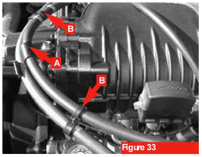
9. Evaporate Canister & Cable Bracket Relocation
Remove the factory throttle cable / evaporative emissions EVAP canister hose bracket and its mounting bolt from your original stock intake manifold. Install this factory bracket directly onto the designated boss on the supercharger housing (see arrow A, Figure 33). Route the throttle cable and EVAP canister hose cleanly through the bracket channels, then secure them tightly using the provided heavy-duty zip ties at the designated anchor points (see arrows B, Figure 33).
2001 Tacoma Drive-By-Wire Provision: For 2001 model year Tacomas equipped with a Drive-By-Wire throttle body, the two lower factory throttle body mounting studs must be extracted from the stock intake and reused on the new supercharger manifold. Use a dedicated stud removal tool or the double-nut method to unthread them carefully without marring the threads. Upon reinstallation, torque both lower securing nuts to 18 ft-lbs (24 Nm).
10. Cable Linkage Reconnection
Slide the barrel ends of the throttle cable and, if applicable, the automatic transmission kickdown cable back into their respective factory linkage tracks on the throttle body butterfly assembly (refer to Figure 8).
11. Cable Bracket Seating
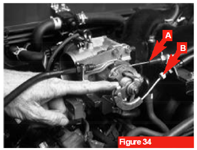
Seat the outer sheaths of the transmission kickdown cable (see arrow A, Figure 34) and the primary throttle cable (see arrow B, Figure 24) securely into the channels of your newly installed upper cable bracket. Hand-tighten the adjustment nuts to hold them in place.
12. Throttle Cable Tension Calibration
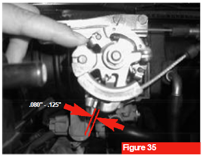
To verify and achieve correct throttle cable deflection and tension, perform the operational check illustrated in Figures 35 and 36:
- The Downward Check: Apply light but firm finger pressure downward on the exposed cable strand (see Figure 35). You should feel and hear a distinct, mechanical "click" as the slack is taken up.
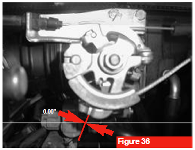
- The Return Check: Release your finger pressure completely. You should immediately hear a secondary "click" as the spring-loaded throttle linkage arm snaps back and cleanly bottoms out flush against its mechanical idle stop bracket (see Figure 36).
- If either click is absent, adjust the positioning nuts on the cable bracket to fine-tune the cable slack until this precise mechanical response is achieved.
13. Driver's Side Bracket & Ground Reassembly
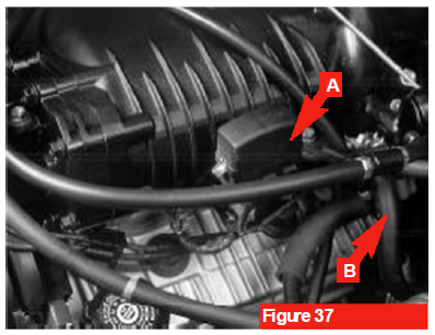
Mount the factory diagnostic plug bracket and the engine ground wire connector onto the designated mounting locations in the driver's side of the supercharger manifold base. Snap the diagnostic data link connector securely back into its original bracket (see arrow A, Figure 37).
14. Fuel Return Line Retention
Reinstall the factory fuel return line mounting bracket to the lower driver's side section of the supercharger manifold (see arrow B, Figure 37.) Secure it tightly using the retained hardware, ensuring the line is routed free of kinks.
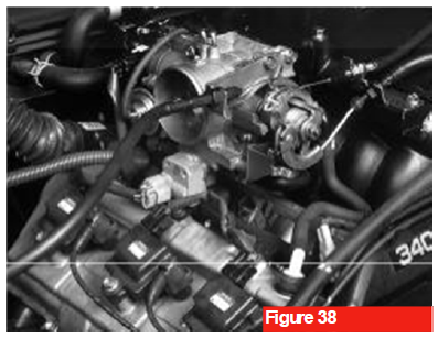
15. Comprehensive Diagram Verification
Using the personal reference sketches/photographs you made during disassembly alongside the dedicated technical schematics at the back of this manual, perform a rigorous double-check of all vacuum hose routing, electrical cable clearance, and bracket orientations (see Figure 38). Correct any routing errors or structural interference before proceeding.
16. Gravel Guard Reinstallation
Position the factory gravel guard underneath the radiator assembly. Secure the panel using its original fasteners to protect the lower engine bay and the newly accessible A/C belt adjustment hardware.
17. Battery Reconnection
Reconnect the negative (ground) battery cable to the negative terminal of the battery. Ensure the connection is tight and free of corrosion.
18. Initial Idle Check & Leak Inspection
Start the vehicle and allow the engine to idle for approximately 15 minutes. While engine runs, closely inspect the engine bay for any fluid leaks (coolant or fuel) and listen carefully for audible vacuum leaks around the manifold gaskets and throttle body.
19. Premium Fuel Labeling
Apply the high visibility "Premium 91+ Octane Fuel Required" decals directly onto the vehicle's fuel gauge cluster and inside the fuel filler door. This serves as a vital reminder to prevent accidental refueling with low-grade gasoline.
20. Belt Routing Decal Placement
Affix the supplied Magnuson belt routing diagram sticker to a clean, highly visible surface on the underside of the vehicle's hood for easy reference during future accessory belt servicing.
21. Initial Road Test Calibration
Conduct a careful, low-load test drive of the vehicle to verify normal transmission shifting, smooth throttle response, and proper instrument cluster operation. If the vehicle drives smoothly and throws no diagnostic trouble codes (CEL), the primary mechanical installation is successful.
22. Post-Installation Diagnostic Drive
Extend the road test to evaluate the vehicle under varying engine loads. Listen closely for any atypical mechanical vibrations, harsh noises, or engine misfires.
Acoustic & Detonation Safety Guidelines
- Normal Supercharger Whine: It is completely normal to hear a distinct, high-pitched mechanical whine emanating from the supercharger assembly when the engine transitions into a boost state.
- Engine Detonation (Pinging): Listen closely for a metallic rattling or "pinging" sound under acceleration. If any engine detonation is heard, immediately lift off the throttle to prevent severe internal engine damage. Detonation is typically caused by residual low-octane fuel remaining in the fuel system lines. Premium 91+ octane fuel must be strictly maintained moving forward.
- System Exception Note: For 2001 or newer model year 4Runners utilizing the electronic Drive-By-Wire throttle system, please skip directly to the supplemental calibration section on the following page.
Phase 6: Supplemental Throttle Body and Air Tube Installation
(Exclusively for 2001 and newer 4Runner models equipped with the electronic Drive-By-Wire throttle system).
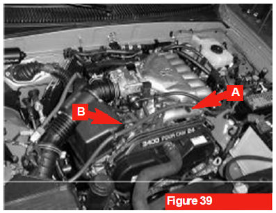
1. Intake Air Box Deconstruction
Locate the factory intake air box assembly. Remove the rubber blocking plug (see arrow A, Figure 39) and disconnect the adjacent vacuum hose (see arrow B, Figure 39). Retain the rubber plug for reassembly; the disconnected vacuum hose is obsolete and will not be reused with the supercharger configuration.
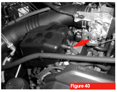
2. Air Box Cap-Off
Install the retained factory rubber plug onto the open air box connection nipple that was exposed during the previous step (see arrow, Figure 40) to seal the intake tract from unfiltered air.
3. Brake Booster Port Relocation
Locate the protective rubber plug onto the open air box connection nipple that was exposed during the previous step (see arrow, Figure 40) to seal the intake tract from unfiltered air.
4. Vacuum Barb Cap-Off
Locate the factory rubber capping plug on the metal vacuum tube assembly situated at the top-rear section of the stock intake manifold. Transfer and secure this plug onto the open vacuum barb located in the flat throttle body mounting flange of the supercharger.
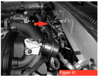
5. Heater Hose Firewall Clearance Modification
Locate the factory molded heater hose assembly running along the vehicle firewall (see arrow, Figure 41). Loosen its mounting retention slightly and rotate the entire assembly approximately 30° upward from its stock position. This adjustment creates the vital physical clearance required to prevent the re-routed valve cover breather hose from rubbing against the hot heater lines.
Phase 7: EGR Valve Disassembly & Reinstallation
(Applicable only to Tacoma or T100 models factory-equipped with an Exhaust Gas Recirculation system)
Removal Procedure
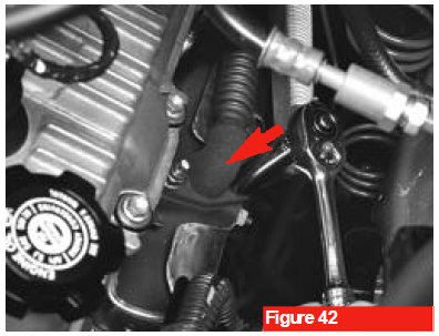
1. EGR Pipe Uncoupling
Loosen the heavy-duty EGR pipe coupling where it connects to the driver's side exhaust manifold (see Figure 42). Loosening this joint provides the necessary articulation and play to simplify the rest of the disassembly and reassembly process.
2. Rear Engine Bracket Loosening
Loosen or completely remove the retaining nut from the structural pipe clamp securing the EGR tube to the back of the cylinder head/engine block assembly.
3. Valve-to-Pipe Disconnection
Remove the two factory hex nuts securing the flange of the EGR pipe to the base of the EGR valve, then carefully separate the two components.
4. Valve-to-Manifold Fastener Removal
Remove the two remaining nuts securing the primary EGR valve housing and its sealing gasket to the threaded studs on the stock intake manifold.
5. Valve Extraction & Bypass Care
Carefully lift the EGR valve and its gasket off the factory manifold studs and set the assembly aside. If extra clearance is needed, you may disconnect the dedicated EGR diagnostic vacuum lines; however, do not disconnect the two coolant bypass hoses plumbed into the valve body.
- Identification Note: The coolant lines are easily identified by their factory spring clamps, whereas the vacuum lines are push-on fitments.
Installation Procedure
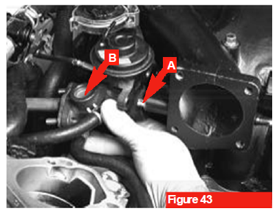
1. Block-Off Plate Removal & Initial Valve Mounting
Unbolt and remove the temporary EGR block-off plate from the two threaded mounting studs on the new supercharger manifold base. Slide the factory EGR gasket and the EGR valve housing over the studs, re-employing the original nuts and washers. Hand-tighten the hardware for now to allow for alignment adjustments (see arrow A, Figure 43).
2. EGR Pipe Alignment
With the main supercharger assembly fully bolted down to the engine block, align the flange of the factory EGR pipe with the EGR valve inlet. Secure the union hand-tight using the original factory nuts (see arrow B, Figure 43).
3. Exhaust Manifold Torque
Fully tighten the EGR pipe coupling nuts at the driver's side exhaust manifold junction (refer to figure 42). Torque these fasteners to the exact specifications outlined in your Toyota Repair Manual.
4. Final Valve & Pipe Torquing
Using a calibrated torque wrench, tighten the EGR-pipe-to-EGR-valve nuts, followed by the EGR-valve-to-manifold nuts, to the final values specified in your Toyota Repair Manual. Ensure even pressure across the flanges to prevent exhaust or vacuum leaks.
5. Rear Pipe Clamp Retention
Reposition the structural EGR pipe alignment clamp over the mounting stud at the back of the engine block. Reinstall the factory retaining nut and tighten it securely.