


Pro Forged Piston Set (+.080" / 94mm) | 12.0:1 Compression
Bring race-proven technology to your high-performance build. Built on over a decade of success with our legendary big-bore forged aluminum piston kits, these pistons are engineered to withstand the rigorous demands of high-RPM racing and extreme operating environments. Proven through years of testing, this premium forged set consistently delivers more horsepower and up to 15% more torque than factory piston sets.
Kit Includes
- Premium Forged Aluminum Pistons
- Lightweight Tool-Steel Chromoly Wrist Pins
- High-Strength Spiral Locks
- Professional-Grade LC Pro Ring Sets
Key Features & Specifications
- Bore Size: 94.00mm (+0.80" Overbore)
- Compression Ratio: High-compression 12.0:1 ratio-ideal for high-performance builds where maximum power and thermal efficiency are required.
- Structural Integrity: Forged construction provides vastly superior tensile strength and thermal resistance to easily withstand the rigorous demands of high-RPM use.
Custom Machining & Installation Notes
- Custom Camshaft Valve Clearance: For builders running aggressive, high-lift, or high-duration aftermarket camshaft profiles, custom piston notching service is available to ensure adequate valve-to-piston clearance. Please see our Notch Labor service for more details or to add this machining service to your build.
- Bore Inspection: Your cylinder block must be precision bored and honed to exactly 94.00mm to achieve this critical piston-to-wall clearances required for high-performance forged alloys. Always provide these pistons to your automotive machinist prior to final block honing.
| Note: Images are for illustration purposes only. Images may not represent the product listed. Please contact customer service with any questions or concerns: 1-928-505-2501. |
- 1985-1995 22R 2.4L Engines
- 1985-1995 22RE 2.4L Engines
CP Forged Piston Set
Follow these standard operating procedures to ensure optimal ring seal, minimal friction, and maximum engine longevity when prepping a cylinder block for CPN and CPN2 piston rings.
Phase 1: Machining & Geometry Setup
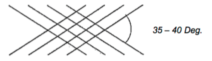
- Verify Equipment Configuration: Set up your honing machine to achieve a final cylinder bore cross-hatch angle between 35° and 40° relative to the horizontal plane.
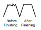
- Execute Plateau Honing: Use a multi-stage grit progression to perform a true plateau hone. This process must successfully shear off the sharp structural peaks left by the initial boring passes while leaving the micro-valleys intact to serve as vital lubrication reservoirs.
Phase 2: Post-Machining Decontamination
- Initial Wash: Before proceeding to final engine assembly, thoroughly scrub the cylinder bores using hot, soapy water and a stiff nylon brush.
- The White-Cloth Test: Wipe the treated cylinder walls with a clean, white lint-free cloth.
- Repeat as Necessary: If any gray or black grit residue is visible on the cloth, repeat the scrub cycle. Bores are not considered clean until the cloth comes out completely spotless.
- Note: Failure to completely remove residual honing grit from the cylinder walls will cause immediate, catastrophic abrasive wear to both the rings and the freshly honed bores during initial startup.
Phase 2: Abrasive Selection & Multi-Stage Grit Progression
To achieve the precise surface roughness required for proper ring seating on gray cast iron engine blocks and Nikasil cylinders, adhere to the following abrasive specifications:
1. Initial Honing Stage: Choose the appropriate stone type based on your shop equipment to establish the core cross-hatch depth:
- Conventional Vitrified Stones: Use #220 - #280 grit
- Diamond Stones: Use #325 - #550 grit
2. Plateau Finishing Stage: After completing the initial honing passes with your primary stones, finish the cylinder walls using one of the following methods to remove jagged structural peaks, torn metal, or folded material:
- Fire Conventional Abrasive: Perform final smoothing passes using a #400 - #600 grit stone.
- Surface Conditioning Sweep: Sweep the cylinder bores using a flexible brush or a specialized nylon-bristle plateau honing tool.
- Warning: Skipping the plateau finishing stage leaves microscopic "peaks" that will instantly shear and destroy the ring face during initial startup. This final conditioning step is mandatory to eliminate jagged material and guarantee proper oil retention.
Phase 3: Surface Roughness Verification Manufacturer Compliance
Before running the final production passes, cross-reference your stone selection with your honing equipment manufacturer to guarantee that the selected grits will achieve the precise micro-finish requirements listed below:
- Mean Roughness Depth: (Rz): 59 - 138 μin (1.5 - 3.5 μm)
- Roughness Average: (Ra): 15 - 35 μin (0.4 - 0.9 μm)
- Warning: Visual inspection alone cannot confirm proper plateau characteristics. You must use a calibrated profilometer to verify that both the Ra and Rz values fall within these exact operational windows. Failing to meet these metrics will cause immediate ring glazing or excessive oil consumption.
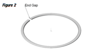
Phase 4: Piston Ring End Gap Verification
Failure to verify and adjust the piston ring end gap prior to final assembly will result in ring-tips expanding, touching, and binding at operating temperature. This will cause catastrophic engine failure, broken ring lands, and severe cylinder wall scoring. This final end gap geometry remains the sole responsibility of the engine builder.
Operational Guidelines
- Application Variables: The specifications provided below are general baseline guidelines. High-stress configurations-including forced induction (turbocharged/supercharged), nitrous oxide, filled blocks, and endurance racing-require increased structural clearance to handle elevated thermal expansion.
If your specific application requires custom variance, contact technical support at 949-567-9000 before clearancing the rings.
Calculation & Conversion Procedure
Before using the application multiplier table, all metric cylinder bores must be converted to inches.
- Convert Bore to Inches: Divide the metric millimeter bore size by 25.4.
- Apply Application Factor: Multiply the resulting inch-bore size by the specific application constant shown in your technical spec sheet.
- Metric Bore (mm) divided by 25.4 = Bore Size (Inches)
- Bore Size (Inches) x Application Factor = Required Target Ring Gap
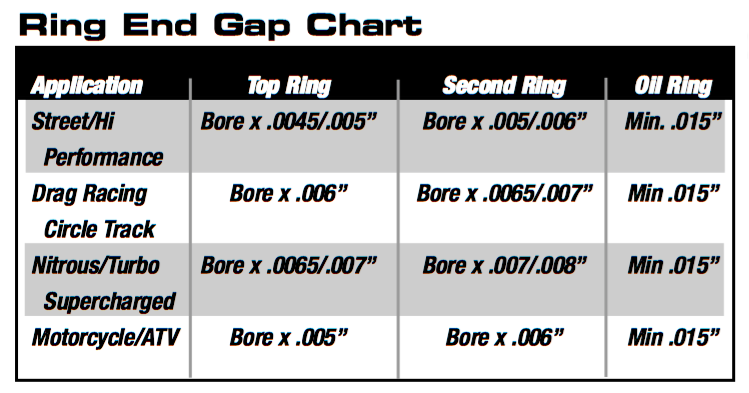
Calculation Example (Street Application Top Ring):
- 81mm divided by 25.4 = 3.189 in
- 3.189 in x 0.005 = 0.016 in target end gap
Phase 5: Piston Ring Gap Measurement Procedures
Visual estimation is strictly prohibited. You must use precision measuring equipment to verify the end gap of every single ring. If the measured ring gap is less than the minimum calculated specification for your exact bore size, you must file-fit the rings to achieve the proper clearance. Failure to do so will result in terminal engine failure.
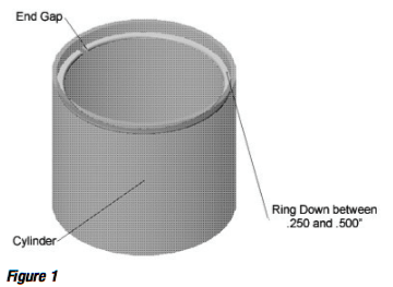
Measurement Setup & Execution
- Install Torque Plate (If Applicable): Bolt the torque plate to the engine block and torque it to factory specifications. This simulates the actual cylinder distortion that occurs when the cylinder head is installed, ensuring your measurements are highly accurate.
- Squaring the Ring: Insert the piston ring into the cylinder bore. Push the ring down below the deck surface, ensuring it is perfectly square to the deck. Using an inverted piston without rings is the recommended method to push the ring down evenly.
- Measure Clearances: Insert a calibrated feeler gauge (or an equivalent precision ring-gap measuring device) into the ring end gap to determine the exact clearance.
Custom Fitting Adjustments
- File-Fitting: If the measured gap falls below your target calculation, use a dedicated piston ring filer to carefully remove material from the ring tips. Always file inward toward the center of the ring to prevent chipping the outer face or coatings.
- Deburring: After filing, lightly deburr the sharp edges of the ring tips with a fine stone to prevent them from scoring the cylinder walls during operation.
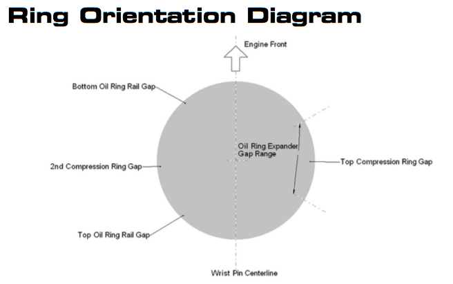
Phase 6: Precision Ring Filing & Orientation Procedures
Incorrect ring orientation or improper filing techniques will disrupt the hydrodynamic oil film, cause severe blow-by, oil consumption and lead to immediate engine damage. Adhere strictly to the marking and structural profiles outlined below during installation.
Mechanical Precision Filing Technicalities
- Tool Requirements: Always use a dedicated manual or electric piston ring filing tool to adjust the end gap.
- Directional Technique: Position the ring firmly against the grinding wheel and file exclusively in an inward direction (from the outside face toward the center of the ring). Filing outward will chip, fracture, or peel the specialized face coatings (such as plasma moly or chrome).
- Squareness Verification: Keep the main ring perfectly square to the filing wheel sides to ensure the finished ring tips remain parallel. Angular or uneven ring ends will distort heat transfer and cause improper gap readings.
- Bore Size Variance Note: Ring sets are precision-manufactured for specific nominal bore diameters. For every 0.001 in the actual cylinder bore measures over the intended manufactured specification, the ring end gap will automatically expand by approximately 0.00314 inches (calculated as Pi multiplied by the bore variance).
- Change In Ring Gap = Change in Bore x 3.1416
2. Second Compression Ring Orientation
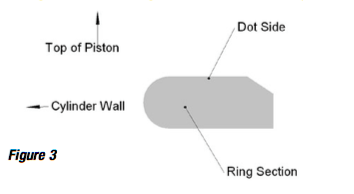
Inspect the second ring surfaces thoroughly and install according to the structural markers present:
- Laser Markings/Dots: If the ring face features a stamped dot, alphanumeric writing, or a manufacturer emblem, install the ring with this side facing up toward the cylinder head.
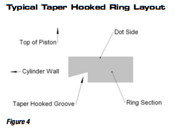
- Taper Hook Groove / Napier Style: If the second ring utilizes a specialized taper hook groove profile, it must be installed with the hook or groove facing down toward the oil pan. This design acts as a mechanical scraper to manage the oil film on the cylinder wall.
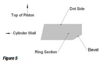
- Internal Bevel Profiles: Unmarked second compression rings featuring an inner chamfer or bevel must be installed with the bevel side facing down toward the oil pan.
- Symmetrical Profiles: Symmetrical rings completely devoid of markings, writing, or internal bevels are bidirectional and can be installed with either side facing up.
3. Three-Piece Oil Control Ring Architecture
Adhere to these exact physical parameters when preparing and seating the multi-piece oil ring assembly.
- Component Configuration: Most high-performance oil rings utilize a three-piece design consistent of two steel scraper rails and a central ventilation expander ring,
- Rail End Gap Limits: Measure the end gap of both the top and bottom scraper rails independently. The gap must not be less than 0.015 inches.
- Expander Care: Ensure the ends of the expander butt together perfectly without overlapping. Do not modify, file, or cut the expander ring under any circumstances. Modifying the expander will destroy the radial tension of the oil ring assembly and cause severe oil consumption.
Legal Disclaimer & Product Warranty Policy
Due to the extreme operating environments and high-stress nature of high-performance and racing applications, all CP Pistons/Pankl products and services are sold strictly "As Is" and "With All Faults."
1. Warranty Exclusion
CP Pistons/Pankl provides no warranty whatsoever, whether express or implied. This includes, but is not limited to, any implied warranties of merchantability or fitness for a particular purpose.
It is expressly understood, agreed upon, and considered a core condition of doing business that the purchaser assumes all risk regarding the selection, quality, performance and use of these components. CP Pistons/Pankl provides all buyers with a full and complete opportunity to inspect and examine all parts, inventory, and services prior to purchase or installation.
2. Limitation of Liability
Under no circumstances shall CP Pistons/Pankl be held liable for any special, incidental, indirect or consequential damages resulting from the sale, installation, modification or use of these products.
Excluded damages for which CP Pistons/Pankl bears no responsibility include, but are not limited to:
- Damage to or loss of other property, engine components, or support equipment.
- Loss of profits, business revenue, or commercial value.
- Costs associated with purchased replacement goods or secondary labor.
- Legal or financial claims made by customers of the primary purchaser.
By retaining and installing these components, the engine builder and end-user explicitly accept these terms in full.

")
