


Pro Forged Piston Set | LCE Performance Engine Components
For more than a decade, our advanced 93mm and 94mm big-bore forged aluminum piston kits have set the standard for high-performance Toyota 20R, 22R, and 22RE builds. Now, that exact same race-proven engineering and metallurgical technology is available for the 2RZ and 3RZ-FE platforms. Precision-machined to withstand the extreme cylinder pressures and thermal stresses of forced induction, high-RPM racing, and sustained track use, these pistons provide the ultimate durability baseline for your bottom-end build.
This premium piston set comes fully loaded and ready for assembly, featuring lightweight tool-steel chromoly wrist pins, heavy-duty spiral locks, and our signature high-performance pro ring sets engineered for optimal cylinder sealing and minimal friction.
Kit Includes
- Premium Forged Aluminum Pistons
- Lightweight Tool-Steel Chromoly Wrist Pins
- High-Strength Spiral Locks
- Professional-Grade Performance Piston Ring Sets
Key Features & Specifications
- Engine Application: Toyota 2RZ (2.4L) / 3RZ-FE (2.7L) 16-Valve DOHC
- Bore Size: 96.00mm (+.040" Overbore)
- Compression Ratio: Low-compression 7.8:1 ratio-engineered specifically for high-boost turbocharging or supercharging applications.
- Structural Integrity: Forged construction provides vastly superior tensile strength and resistance to detonation compared to factory cast or hypereutectic pistons.
Custom Machining & Installation Notes
- Custom Camshaft Valve Clearance: For builders running aggressive, high-lift, or high-duration aftermarket camshaft profiles, custom piston notching service is available to ensure adequate valve-to-piston clearance. Please contact our sales department directly prior to ordering to add this machining service to your build.
- Bore Inspection: Your cylinder block must be precision bored and honed to exactly 96.00mm to achieve the critical piston-to-wall clearances required for forced-induction forged alloys. Always provide these pistons to your automotive machinist prior to final block honing.
| Note: Images are for illustration purposes only. Images may not represent the product listed. Please contact customer service with any questions or concerns: 1-928-505-2501. |
- 1995.5-2004 3RZ 2.7L Engines (Boosted)
CP Forged Piston Set
To achieve optimal cylinder sealing, rapid ring seating, and maximum oil control when utilizing our premium CPN and CPN2 high-performance piston ring sets, precision cylinder all preparation is essential.
To achieve the precise surface profile required for optimal ring seating on gray cast iron engine blocks or Nikasil cylinders, honing equipment manufacturers recommend a two-step conditioning process.
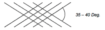
Initial Cross-Hatch Honing
Begin the sizing and cross-hatch process using one of the following abrasive specifications:
- Conventional Vitrified Stones: #220 to #280 grit
- Diamond Stones: #325 to #550 grit
Final Plateau Finishing
After establishing the initial cross-hatch with your primary conventional or diamond abrasive, the bore surface must be plateaued to remove microscopic, jagged peaks and eliminate any folded or torn metal matrix. Finish the cylinder walls utilizing one of the following methods:
- Fine Grit Conventional Stone: #400 to #600 grit abrasive sweep
- Flexible Honing Brush/Nylon Bristle Plateau Tool: Mild bore sweep to clean and smooth the surface finish.
Critical Machinist Note: Prior to final block preparation, always verify your honing equipment or abrasive manufacturer that your selected stone grit and pressure cycle will produce the exact surface finish parameters listed below.
- Rz (Mean Roughness Depth): 59 to 138 micro-inches (1.5 to 3.5 micrometers)
- Ra (Roughness Average): 15 to 35 micro-inches (0.4 to 0.9 micrometers)
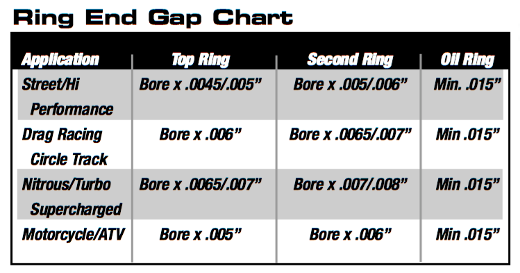
Cp Piston Ring End Gap Guidelines & Technical Warning
Failure to properly check and set the piston ring end gap prior to final engine assembly can result in catastrophic engine failure.
The clearance recommendations provided in the guide below are general industry guidelines. The optimal ring gap for any specific engine variant or custom build will vary based on its intended use. Increased ring end gaps are strictly required for high-stress applications, including:
- Forced Induction (Turbocharged or Supercharged)
- Nitrous Oxide Systems
- Hard-Blok / Filled Engine Blocks
- Endurance Racing & Extreme Track Use
The final determination and execution of the proper ring end gap is the sole responsibility of the engine builder. If you have any technical questions regarding your specific clearance setup, please contact the manufacturer's technical support line directly at 949-567-9000.
How to calculate Piston Ring End Gap
To determine your required ring end gap, first locate your specific driving application in the reference table below.
Important: All metric cylinder bore measurements must be converted into imperial inches before applying the gap factor.
Calculation Formula & Example
- Convert Bore to Inches: Divide your metric millimeter (mm) bore size by 25.4.
- Apply Application Factor: Multiply that total by the specific application clearance factor found in the reference table.
Ex: Finding the top ring end gap for an 81mm bore street engine:
- Conversion: 81mm / 25.4 = 3.189 inches.
- Gap Factor: 3.189 inches x 0.005 (Street Factor) = 0.016" Required End Gap
Piston Ring Installation & Measurement Procedures
The procedures below are general guidelines for proper piston ring installation. Specific high-performance or forced-induction setups may require alternative clearances. Always consult the technical charts and diagrams included with your ring pack before final assembly.
Step-by-Step Ring Gap Measurement
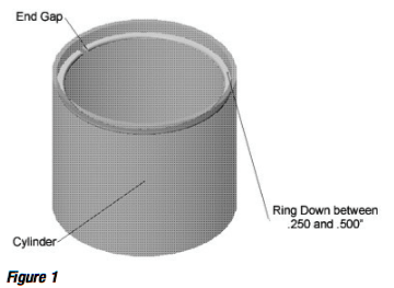
- Install a Torque Plate (Highly Recommended): If applicable to your engine platform, a torque plate must be bolted to the block and torqued to factory specifications before measuring to simulate real cylinder distortion under cylinder head clamping loads.
- Square the Ring in the Bore: Position the individual piston ring below the deck surface. Ensure it is entirely square to the bore by using a squaring tool or an inverted piston to push the ring down evenly. (See figure 1)
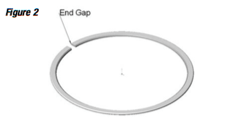
- Measure Clearances: Insert a calibrated feeler gauge or equivalent precision measuring tool into the ring end gap to determine your current clearance. (See Figure 2)
-Filing Note: If your measured ring gap is less than the minimum clearance specified for your particular cylinder bore size and application factor, it is mandatory to custom file-fit the piston rings using a dedicated ring filer to achieve the correct safe end gap.
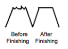
Ring Filing Procedures:
- Use the Proper Equipment: Piston ring end gaps must be modified using a dedicated mechanical or electric ring gap filing tool.
- Filing Direction: Always file the ring face in an inward direction (from the outside edge toward the center of the ring). This prevents the abrasive wheel from chipping or peeling the specialized outer coatings (such as plasma-moly or chrome) away from the ring face.
- Keep Ends Square: Ensure the ring end is kept perfectly square and flat relative to the filing wheel to maintain an even gap across the entire mating surface.
-Bore Size Note: Performance ring sets are engineered to fit precise cylinder bore diameters. For every 0.001" overbore beyond the ring's intended spec, the ring end gap will automatically expand by approximately 0.00314".
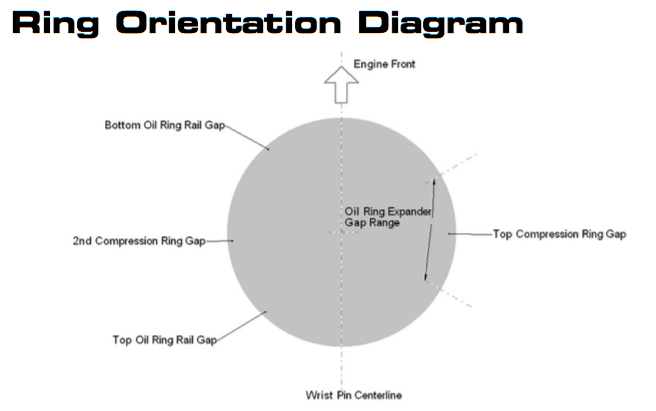
Top Piston Ring Orientation & Identification
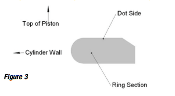
Before seating the top compression ring onto the piston, inspect the faces and edges carefully to determine the correct directional orientation
- Marked Rings: If the top ring features a laser-etched dot, number or manufacturer writing on the flat surface, it must be installed with the marked side facing up toward the cylinder head.
- Inner Beveled Rings (Unmarked): If the ring is unmarked but features an internal bevel cut along the inner top radius, it must be installed with the bevel facing up.
- Symmetrical Rings: If the ring completely lacks a dot, writing, or internal bevel, it is symmetrical and can be installed with either side facing up.
Top Ring:
Before seating the top compression ring onto the piston, inspect the faces and edges carefully to ensure correct orientation
- Marked Rings: If the ring has a stamped dot, part number or writing, it must be installed with the marked side facing up (toward the cylinder head).
- Inner Beveled Rings (Unmarked): If the ring is completely unmarked but features a cut-out bevel along the inner diameter, it must be installed with the bevel side facing up.
- Symmetrical Rings: If the ring lacks a dot, writing, or internal bevel, it is entirely uniform and can be installed with either side facing up.
Second Ring:
Before seating the second scraper/compression ring into the piston, inspect the profile carefully to ensure proper downward oil management.
- Marked Rings: If the ring features a stamped dot, letter, or manufacturer writing, it must be installed with the marked side facing up (toward the cylinder head).
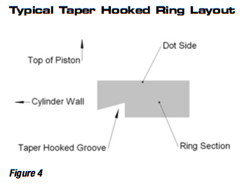
- Taper Hook / Napier Style Rings: If the ring features a stepped or hook-groove cut on its outer edge, the groove must always face down toward the oil pan. (See Figure 4)
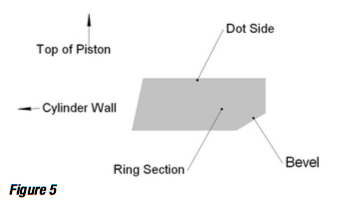
- Inner Beveled Rings (Unmarked): If the ring is unmarked but features a cut-out bevel along the inner diameter, it must be installed with the bevel side facing down. (See Figure 5)
- Symmetrical Rings: If the ring lacks a dot, writing, hook groove, or internal bevel, it is completely uniform and can be installed with either side facing up.
Oil Ring:
Most premium CP oil ring packs utilize a high-efficiency three-piece construction consisting of two steel side rails and a central expander ring.
- Rail End Gaps: Before final assembly, verify that the end gaps on both the top and bottom oil rails are a minimum of 0.015". The rail ends must butt cleanly without overlapping.
- Expander Care: The central expander ring provides the precise outward tension required for proper cylinder oil scavenging. Do not modify, trim, or file the expander ring under any circumstances.
Product Disclaimer & Warranty
Due to the extreme stress of high-performance and racing applications, all CP-Carillo/Pankl products are sold "as-is" and "with all faults," without any express or implied warranty of merchantability or fitness for a particular purpose.
By purchasing these components, the buyer acknowledges that they have had a full opportunity to inspect the parts and accepts them in their current condition.
- CP-Carillo / Pankl shall not, under any circumstances, be liable for any special, incidental, or consequential damages.
- This includes, but is not limited to:
- Damage to or loss of other engine components, equipment, or property.
- Loss of profits, revenue, or vehicles down-time.
- Costs associated with replacement goods or labor.
- Third-party claims resulting from the sale, installation, or use of these high-performance parts.
- The final selection, proper installation, and ultimate use of these racing products remain the sole responsibility of the engine builder and end user.

")
