


Pro Forged Piston Set | 12.5:1 Compression (+.040)
Bring race-proven technology to your Toyota 2RZ or 3RZ engine. Built on over a decade of success with our legendary 20R, 22R, and 22RE big-bore forged aluminum piston kits, these pistons are engineered to withstand the rigorous demands of high-RPM racing and high-performance operation.
Kit Includes
- Premium Forged Aluminum Pistons
- Lightweight Tool-Steel Chromoly Wrist Pins
- High-Strength Spiral Locks
- Professional-Grade Performance Piston Ring Sets
Key Features & Specifications
- Engine Application: Toyota 2RZ (2.4L) / 3RZ-FE (2.7L) 16-Valve DOHC
- Bore Size: 96.00mm (+0.40" Overbore)
- Compression Ratio: High-compression 12.5:1 ratio-ideal for high-compression, naturally aspirated racing builds requiring maximum thermal efficiency and power output.
- Structural Integrity: Forged construction provides vastly superior tensile strength and thermal resistance compared to factory cast or hypereutectic pistons.
Custom Machining & Installation Notes
- Custom Camshaft Valve Clearance: For builders running aggressive, high-lift, or high-duration aftermarket camshaft profiles, custom piston notching service is available to ensure adequate valve-to-piston clearance. Please see our Notch Labor service for more details or to add to your build.
- Bore Inspection: Your cylinder block must be precision bored and honed to exactly 96.00mm to achieve the critical piston-to-wall clearances required for high-performance forged alloys. Always provide these pistons to your automotive machinist prior to final block honing.
| Note: Images are for illustration purposes only. Images may not represent the product listed. Please contact customer service with any questions or concerns: 1-928-505-2501. |
- 1995.5-2004 2RZ 2.4L Engines
CP Forged Piston Set
For engine builds utilizing 94mm CP Pistons with CPN or CPN2 piston rings, achieving the correct cylinder wall finish is critical to ensure rapid ring seating, optimal oil retention, and maximum compression sealing.
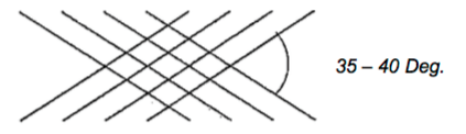
Recommended Honing Media & Finishing Procedures
To achieve the required surface roughness targets on gray cast iron engine blocks or Nikasil cylinders, honing equipment manufacturers recommend a two-stage process using specific abrasive grits.
Stage 1: Initial Honing Abrasives
Select one of the following stone types to establish the baseline cross-hatch pattern and depth:
- Conventional Stones: #220-#280 grit
- Diamond Stones: #325-#550 grit
Stage 2: Plateau Finishing
After the initial hone is completed, you must smooth the cylinder walls to eliminate jagged peaks, folded metal, and torn material left behind by the coarser stones. Finalize the bores using one of these three methods.
- A fine-grit conventional abrasive (#400-#600 grit)
- A sweep of the bores using a flexible honing brush
- A specialized nylon-bristle plateau honing tool
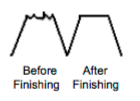
-Technical Note: Always verify with your honing equipment manufacturer that your specific stone grits will accurately produce the required surface roughness targets:
Rz Surface Finish: 59 - 138 μin (1.5 - 3.5 μm)
Ra Surface Finish: 15- 35 μin (0.4-0.9 μm)
CP Piston Ring End Gap Recommendations:
The guidelines provided below are general industry recommendations. The optimal ring gap varies significantly depending on your specific engine configuration and application. Enhanced clearances are typically required for high-stress environments, including forced induction (turbocharged or supercharged), nitrous oxide systems, filled blocks, and endurance racing. Determining and verifying the final correct end gap is the sole responsibility of the engine builder.
For additional technical support, please contact customer service directly at 949-567-9000.
-Critical Safety Notice: Failure to properly check and set the piston ring end gap can result in catastrophic engine failure.
How to Calculate Your Ring End Gap
To determine your required ring end gap, first locate your specific driving application in the target specification chart.
-Note: All metric cylinder bore measurements must be converted to inches before applying the gap factor.
Step-by-Step Calculation
- Convert Bore to Inches: Divide the metric bore size (mm) by 25.4. Apply
- Application Factor: Multiply the resulting bore size in inches by the specific application clearance multiplier provided in your spec sheet.
Example Calculation (81mm Bore for a Standard Street Application):
- Step 1: 81mm / 25.4 = 3.189 inches
- Step 2: 3.189 x 0.005 = 0.016" target end gap
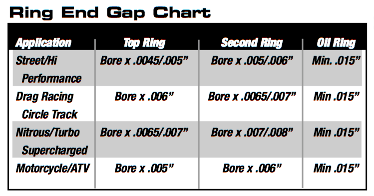
Piston Ring Specifications & Gap Measuring Procedures:
The following instructions outline the standard technical procedures for verifying piston ring end gap. Because high-performance or specialized applications may require unique clearances, always consult the included engineering charts and diagrams prior to final installation.
Step-by-Step Ring Gap Measurement
- Torque Plate Installation: If applicable to your specific engine build, install a torque plate onto the block and torque it to factory specifications. This simulates true cylinder distortion and bore roundness during actual engine operation.
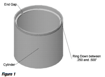
- Squaring the Ring: Carefully insert the piston ring into the cylinder bore. Ensure the ring is positioned below the deck surface and completely square to the bore walls. (See Figure 1)
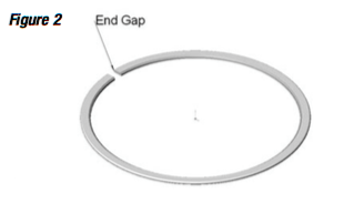
- Measuring the Gap: Insert a precision feeler gauge (or an equivalent ring-gap measuring tool) into the gap to measure the distance between the ring ends. (See Figure 2).
-Important: If your measured ring gap is less than the minimum specification required for your specific bore size, it will be necessary to file-fit the rings to achieve the proper end gap. Failure to do so can cause the ring ends to butt together under thermal expansion, leading to severe cylinder scoring or catastrophic engine damage.
Piston Ring Filing Procedures
When file-fitting your piston rings, accuracy and correct technique are critical to ensure a proper seal and prevent cylinder damage.
- Use the Right Equipment: Always use a dedicated manual or electric piston ring-gap filing tool.
- Filing Direction: Always file the ring end in an inward direction (from the outside face of the ring toward the inside). Filing outward can chip or damage premium outer coatings.
- Keep it Square: Ensure the ring ends remain completely square and parallel to one another during the filing process.
-Bore Size Note: Performance ring sets are manufactured to precision tolerances for specific bore diameters. For every 0.001" the cylinder bore is oversized or worn beyond its intended specification, the ring end gap will naturally increase by 0.00314".
Top Compression Ring Installation & Orientation
Before installing your top compression ring, closely inspect the ring faces and edges for markings, bevels, or grooves.
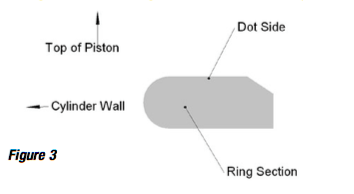
- Marked Rings: If the ring features a dot, laser etching, or writing, always install the ring with this marked side facing UP toward the cylinder head.
- Unmarked Rings with an Inner Bevel: If the ring is completely unmarked but features a cut bevel along the inside edge, install the ring with the bevel side facing UP toward the cylinder head.
- Completely Unmarked / Uniform Rings: If the ring has no dot, writing, or inner bevel, it is symmetrical and can be installed with either side facing up.
Second Compression Ring Installation & Orientation:
Before installing the second compression ring, carefully inspect the ring faces and edges for markings, grooves, or bevels. Proper orientation is essential to ensure effective oil control and prevent compression blow-by. Install the ring according to the following guidelines:
- Marked Rings: If the ring features a dot, laser etching, or writing, always install the ring with the marked side facing UP toward the cylinder head.
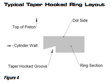
- Taper Hook Groove Style (Scraper Ring): If the ring features a taper hook groove along its outer edge, the groove must always face DOWN toward the oil pan. (See Figure 4)
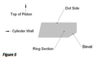
- Unmarked Rings with an Inner Bevel: If the ring is completely unmarked but features a cut bevel along the inside edge, install the ring with the bevel side facing DOWN toward the oil pan. (See Figure 5)
- Completely Unmarked/Uniform Rings: If the ring has no dot, writing, hook groove, or inner bevel, it is completely symmetrical and can be safely installed with either side facing up.
Oil Ring Installation & Specifications:
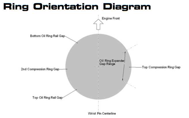
Most CP oil ring assemblies utilize a three-piece design consisting of two thin steel rails and a center expander ring. Proper installation is critical to ensure optimal oil control and prevent cylinder wall scoring.
- Rail End Gap Clearance: Ensure the end gaps on both the upper and lower oil rails are a minimum of 0.015".
- Rail Alignment: The ends of the rails must never butt together or overlap during installation.
- Expander Modification: Do not cut, file, or modify the center expander ring in any way. The expander relies entirely on its factory-engineered tension to properly support the rails and maintain correct tension against the cylinder wall.
Product Disclaimer & Limitation of Liability
Due to the extreme operating conditions and high thermal/mechanical stresses inherent in automotive racing and high-performance environments, all CP Pistons/Pankl products and services are sold strictly "as is" and "with all faults."
1. Exclusion of Warranties
There are no warranties, express or implied, extended with these products. This explicitly excludes any implied warranty of merchantability or fitness for a particular purpose.
As a core condition of doing business and an essential part of the bargain of sale, the purchaser assumes all risk. The buyer takes full responsibility for selecting, evaluating, and verifying that all parts and services are appropriate for their specific engine application.
CP Pistons/Pankl provides every purchaser with a complete opportunity to inspect and examine all parts, inventory, and engineering services prior to final purchase or installation.
2. Limitation of Liability
CP Pistons/Pankl shall not, under any circumstances, be held liable for any special, incidental, or consequential damages. This strict limitation of liability includes, but is not limited to:
- Damage to, or operational failure of, other engine components, auxiliary equipment, or vehicle property.
- Loss of anticipated business profits, commercial revenue, or performance opportunities.
- Costs associated with vehicle down-time, specialized mechanical labor, or acquiring replacement goods.
- Third-party claims brought against the purchaser by their own customers.
These liability exclusions apply absolutely to any and all outcomes arising from the distribution, sale, installation, modification, or track use of these components.


